
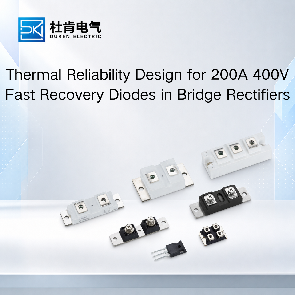
Thermal Reliability Design for 200A 400V Fast Recovery Diodes in Bridge Rectifiers
For industrial rectifier manufacturers, knowing how to improve thermal management of a 200A 400V fast recovery diode is essential for maintaining stable operation under continuous high-current loads. A diode can meet its nominal 200A and 400V ratings yet still experience excessive junction temperature because of forward conduction loss, reverse recovery, poor stud mounting, insufficient heat-sink capacity, or high ambient temperature. These issues are especially relevant in bridge rectifiers used in welding power supplies, industrial DC systems, battery equipment, motor drives, and power converters. Instead of treating overheating as a cooling problem alone, engineers should examine the complete relationship between semiconductor characteristics, bridge configuration, mounting structure, current waveform, and thermal path.
For procurement teams, this also means that selecting a replacement diode requires more than finding the same package and current rating. Thermal compatibility should be verified before volume purchasing.
Bridge Rectifier Configuration Changes the Thermal Design
A bridge rectifier uses multiple diodes to convert AC input into DC output. Depending on the topology, more than one diode can conduct in the active current path at the same time. This means total bridge loss must be considered rather than calculating the temperature of one diode in isolation.
Forward conduction loss remains one of the main heat sources. A useful first approximation is:
Pcond ≈ VF × IF(avg)
If two diodes conduct in the current path, their combined voltage drop contributes to the total rectifier loss. At high current, even relatively small differences in VF can therefore influence heat-sink requirements.
This is one reason a brand Vishay equivalent glass-metal seal housing low conduction loss 200A 400V fast recovery diode should be evaluated using actual forward characteristics rather than nominal ratings alone.
When replacing an established device, engineers should compare VF at relevant current and temperature conditions. A lower room-temperature value does not necessarily describe behavior at elevated junction temperature.
The current waveform also matters.
The 200A rating should not be interpreted as an unconditional ability to carry 200A continuously under any mounting condition. Diode current ratings depend on the conditions specified by the manufacturer, including case temperature, waveform, cooling, and package construction.
A bridge rectifier supplying a relatively continuous industrial DC load can therefore have different thermal requirements from the same diode used as a freewheeling or commutation device in a switching converter.
Understanding the actual conduction duty is the first step toward determining realistic semiconductor loss.
Thermal Design for a 3/4″-16UNF Stud Type Bridge Rectifier
Mechanical construction becomes particularly important when a bridge is assembled from individual stud-mounted power diodes.
A 3/4″-16UNF stud type for bridge rectifier module stud mount DO-9 200A 400V fast recovery diode can use its threaded stud for mechanical installation while also providing an important thermal path from the semiconductor package into the heat sink.
Poor mounting can compromise this path.
The mounting surface should be clean and mechanically suitable for the package. Surface contamination, damage, or poor contact can introduce additional thermal resistance between the diode and heat sink.
Mounting torque should follow the manufacturer's specified value. A torque used for another DO-9-style product should not automatically be transferred to a replacement device simply because the dimensions appear similar.
Polarity must also be verified.
Stud diodes are available in different polarity configurations, and the stud may be electrically connected to the anode or cathode depending on the specific part. This becomes particularly important when multiple devices are installed on conductive heat sinks to create a bridge circuit.
A 3/4″-16UNF stud type for bridge rectifier module stud mount DO-9 200A 400V fast recovery diode may therefore be electrically unsuitable for an existing assembly even when its dimensions fit perfectly if the stud polarity is different.
Where electrical isolation is necessary, engineers must consider both dielectric strength and thermal performance of the insulating interface. Adding an insulating washer or pad can increase thermal resistance and raise junction temperature.
For procurement teams, package dimensions, stud thread, polarity, mounting requirements, and thermal resistance should consequently be confirmed before calling two devices mechanically interchangeable.
Improve Heat-Sink Performance Without Simply Increasing Size
A larger heat sink is not always the most effective solution to diode overheating.
Engineers should first identify where the dominant thermal resistance occurs.
A simplified junction-temperature relationship is:
Tj = Tc + P × Rth(j-c)
The complete thermal system also includes the case-to-heat-sink interface and the heat-sink-to-ambient path.
If the diode case is much hotter than the heat sink close to the mounting point, the interface deserves investigation. If both the diode and heat sink become very hot, the heat sink or airflow may be insufficient for the total power being dissipated.
Bridge assemblies require additional attention because several semiconductor devices can heat the same cooling structure simultaneously.
The thermal design should therefore use total rectifier loss rather than assuming that each diode experiences an independent ambient environment.
Forced-air cooling can improve performance, but airflow distribution is critical. A fan may have an impressive airflow specification while producing limited improvement if cabinet geometry prevents air from passing effectively through the heat-sink fins.
Engineers should also consider neighboring heat sources. Transformers, IGBT modules, inductors, and resistors can increase inlet-air temperature around the rectifier.
These practical issues are central to how to improve thermal management of a 200A 400V fast recovery diode in real industrial equipment.
The cooling design should also include margin for dust accumulation, filter blockage, fan degradation, and higher seasonal ambient temperatures. The maximum permitted junction temperature should be treated as a limit rather than a preferred continuous operating point.
Switching Speed and Leakage Matter in Industrial Power Converters
Not every bridge rectifier operates only at line frequency. In converter stages where diodes experience rapid commutation, reverse recovery can become an important source of additional loss.
A high switching speed industrial power converter low reverse leakage current 200A 400V fast recovery diode should be selected using recovery characteristics appropriate for the actual switching environment.
When a silicon PN diode changes from forward conduction to reverse blocking, stored charge must be removed. Qrr, trr, and peak recovery current help characterize this process.
Higher recovery current can increase stress on the associated switching transistor. This means diode selection can influence IGBT or MOSFET temperature as well as diode temperature.
A high switching speed industrial power converter low reverse leakage current 200A 400V fast recovery diode should consequently be tested as part of the complete commutation circuit.
Reverse leakage also deserves attention, especially at elevated temperature. Leakage generally increases as junction temperature rises, so datasheet comparisons should use equivalent test voltage and temperature conditions.
Low leakage can be desirable for blocking performance, but it should not be considered independently from VF and recovery behavior.
A diode optimized for extremely low leakage but unsuitable recovery performance may still be a poor choice for a fast industrial converter.
The objective is to achieve a balanced combination of conduction loss, recovery performance, blocking capability, thermal resistance, and package compatibility.
FRD, Standard Rectifier Diode and SiC: Which Runs Cooler?
Technology comparison should always begin with operating frequency and circuit function.
A conventional silicon rectifier diode can be an effective solution for line-frequency bridge rectification. In these applications, low forward loss, strong surge capability, mature packaging, and cost can be more important than very fast recovery.
A silicon FRD becomes more useful when the circuit requires faster commutation. Reduced recovery time and charge can lower switching-related losses compared with a standard slow rectifier diode.
SiC Schottky diodes provide much lower minority-carrier reverse recovery and can significantly reduce switching losses in high-frequency converters. They can also reduce turn-on stress on associated transistors.
However, SiC is not automatically the best replacement in every 200A system.
For a legacy bridge built around stud-mounted silicon devices, changing semiconductor technology can introduce package, conduction-loss, surge, cost, and mechanical compatibility questions.
A brand Vishay equivalent glass-metal seal housing low conduction loss 200A 400V fast recovery diode may be more practical when an OEM needs to maintain the existing bridge architecture and heat-sink structure.
For new high-frequency converters, SiC deserves stronger consideration when its lower switching losses create a meaningful efficiency and thermal benefit at the system level.
Conclusion
A reliable strategy for how to improve thermal management of a 200A 400V fast recovery diode must consider the complete bridge rectifier rather than the diode alone.
Forward voltage and current waveform determine a significant portion of conduction loss. Reverse recovery becomes increasingly important in faster converters, while package thermal resistance, stud mounting, electrical isolation, heat-sink capacity, and airflow determine how effectively heat is removed.
For stud-mounted bridge rectifiers, correct polarity and mechanical installation are particularly important. For switching converters, Qrr and trr should be evaluated alongside VF and reverse leakage.
Industrial buyers should therefore qualify candidate diodes under representative electrical and thermal conditions before bulk procurement. A replacement that matches 200A, 400V, and package dimensions is only a starting point; reliable operation depends on whether the complete diode, mounting, cooling, and converter system works together with sufficient thermal margin.
FAQ
Q1: Why can a bridge rectifier generate more heat than expected from one diode?
Multiple diodes can contribute conduction loss during rectification, and several devices may share the same cooling structure. Total bridge loss should therefore be included in thermal calculations.
Q2: Can any DO-9 stud diode replace another with the same thread?
No. Polarity, dimensions, VF, recovery characteristics, thermal resistance, voltage rating, current rating, and mounting requirements must also be checked.
Q3: Is forced-air cooling always necessary for a 200A diode?
Not necessarily. The cooling method depends on actual semiconductor loss, duty cycle, ambient conditions, heat-sink performance, and allowable junction temperature.
Q4: Why does reverse recovery matter to the IGBT or MOSFET?
During diode recovery, the switching transistor may carry additional current when it turns on, increasing switching energy and thermal stress.
Q5: Should SiC replace a silicon FRD in every high-power converter?
No. SiC can provide major recovery advantages at high frequency, but conduction loss, package availability, surge capability, mechanical compatibility, cost, and application requirements must also be considered.
READ MORE:
Procurement and Qualification Guide for Qrr in 200A 400V Fast Recovery Diodes
Qrr and Thermal Reliability in 200A 400V Fast Recovery Diodes for Industrial Power Systems
How to Compare Qrr Specifications When Selecting a 200A 400V Fast Recovery Diode
How Qrr Affects Switching Loss and IGBT Stress in 200A 400V Fast Recovery Diodes
Understanding Qrr in 200A 400V Fast Recovery Diodes: What Industrial Buyers Must Know
Preventing Overheating and Extending Service Life of 200A 400V Fast Recovery Diodes
Reverse Recovery Loss and Cooling Optimization for 200A 400V Fast Recovery Diodes
Reducing Junction Temperature in 200A 400V Fast Recovery Diodes Through Package and Mounting Design
How to Improve Thermal Management of a 200A 400V Fast Recovery Diode in Industrial Power Converters