
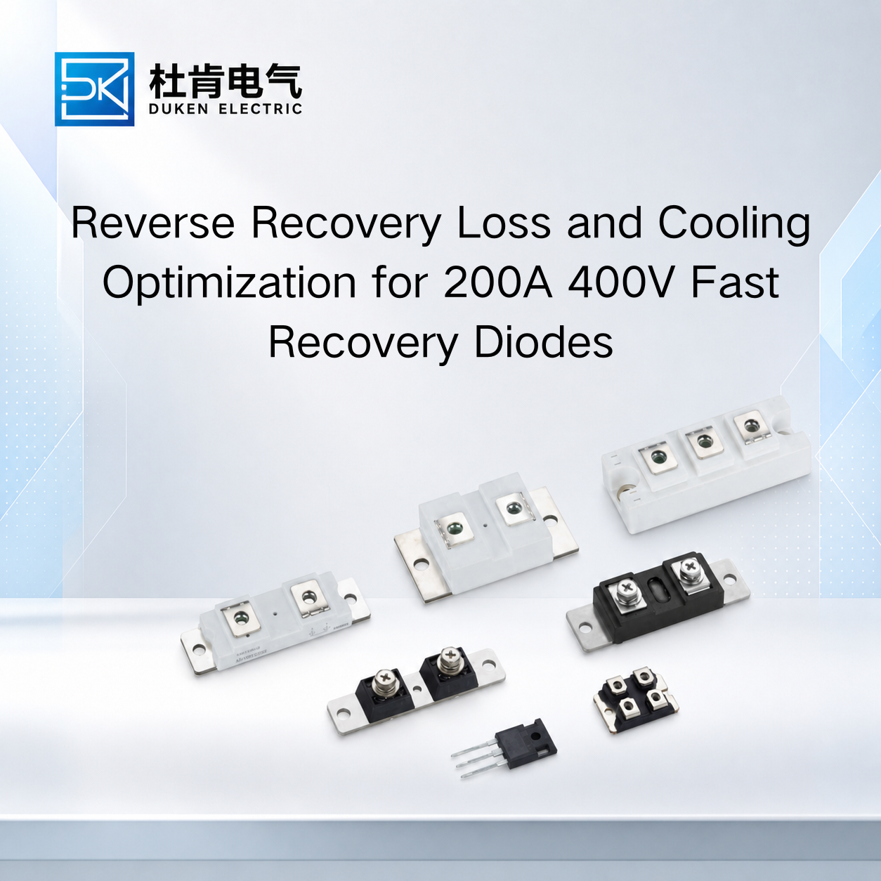
Reverse Recovery Loss and Cooling Optimization for 200A 400V Fast Recovery Diodes
One of the most effective ways to understand how to improve thermal management of a 200A 400V fast recovery diode is to look beyond the heat sink and examine what happens during switching. In industrial inverters, welding power supplies, UPS systems, motor drives, and high-power DC converters, a silicon fast recovery diode generates heat through both forward conduction and reverse recovery. At 200A-class current levels, these losses can become substantial, particularly as switching frequency increases. For engineers and procurement managers, selecting a diode with suitable VF, Qrr, trr, leakage current, and package thermal resistance can therefore reduce junction temperature before any changes are made to fans or heat sinks.
Thermal optimization should begin with the electrical source of the losses and then continue through the complete cooling path from the semiconductor junction to the surrounding environment.
Why Reverse Recovery Can Become a Thermal Problem
During forward conduction, a silicon PN fast recovery diode stores charge within its semiconductor structure. When the circuit applies reverse voltage, this stored charge must be removed before the diode can fully recover its reverse-blocking capability.
During this interval, reverse current flows.
The recovery process is commonly described using parameters such as reverse recovery time, trr, reverse recovery charge, Qrr, and peak reverse recovery current. These characteristics influence both the diode and the switching device that commutates current away from it.
A high switching speed industrial power converter low reverse leakage current 200A 400V fast recovery diode should therefore be evaluated using more than trr alone.
A very short recovery time can appear attractive, but trr values from different manufacturers may be measured under different forward current, di/dt, reverse voltage, and temperature conditions. Qrr and the shape of the recovery waveform can provide additional information about actual switching behavior.
Switching-related power loss increases with switching frequency. A simplified relationship is:
Psw ≈ Esw × fs
where Esw represents energy associated with each switching event and fs is switching frequency.
This is why a diode that operates comfortably in a lower-frequency industrial rectifier may become thermally stressed when used in a much faster converter.
The associated IGBT or MOSFET can also experience additional turn-on current because it must handle part of the diode's reverse recovery process. Selecting an appropriate FRD can therefore reduce thermal stress across the complete switching cell rather than only lowering diode temperature.
Balance Forward Voltage and Recovery Performance
Reverse recovery is only one part of total semiconductor loss.
During forward conduction, a first-order loss estimate can be written as:
Pcond ≈ VF × IF(avg)
At high current, forward voltage has a direct influence on heat generation. This makes low conduction loss particularly attractive for applications with long conduction periods.
A brand Vishay equivalent glass-metal seal housing low conduction loss 200A 400V fast recovery diode should therefore be compared with the original device at relevant current and temperature conditions.
However, procurement teams should avoid selecting an equivalent based only on the lowest VF shown in a product table.
Power diode design involves trade-offs. A device optimized strongly for conduction characteristics may not necessarily provide the recovery behavior required by a particular switching topology. The most suitable choice depends on the balance between conduction loss and switching-related loss.
For a lower-frequency converter with long conduction periods, VF may have greater influence on average junction temperature. As frequency increases, Qrr and reverse recovery behavior can become increasingly important.
A brand Vishay equivalent glass-metal seal housing low conduction loss 200A 400V fast recovery diode should therefore be qualified using the actual converter rather than through a single datasheet parameter.
Engineers should compare case temperature, switching waveforms, reverse recovery current, and the temperature of the associated transistor under the same operating conditions.
This system-level comparison is much more useful than declaring one diode superior because it has either a lower VF or shorter trr.
Improve Thermal Performance of Stud-Mounted Bridge Rectifiers
Mechanical installation becomes especially important when high-current diodes are mounted directly to a heat sink or conductive rectifier structure.
A 3/4″-16UNF stud type for bridge rectifier module stud mount DO-9 200A 400V fast recovery diode can provide a mechanically robust solution for industrial rectifiers, but the stud connection becomes part of the thermal path.
The quality of the mounting surface matters. Dirt, oxidation, physical damage, or an uneven surface can increase contact resistance and interfere with heat transfer.
Mounting torque should follow the manufacturer's specification. Applying too little torque can result in poor contact, while excessive torque may mechanically stress the stud or package.
Electrical configuration should also be verified. Depending on the diode version, the stud can be associated with the anode or cathode. This affects bridge construction and determines whether the mounting structure can be electrically common or must be isolated.
A 3/4″-16UNF stud type for bridge rectifier module stud mount DO-9 200A 400V fast recovery diode should therefore be checked mechanically and electrically before it is treated as a direct replacement.
When electrical isolation is necessary, engineers should evaluate the thermal consequences of the insulating interface. A high dielectric-strength material is not automatically an effective thermal interface.
Heat generated in the junction must pass through every layer between the semiconductor and cooling system. Increasing thermal resistance at any one interface raises junction temperature for the same semiconductor loss.
This is one reason package and mechanical compatibility deserve attention during procurement, even when electrical ratings already appear suitable.
Heat Sink and Airflow Should Be Designed for Worst-Case Operation
Once diode losses and mounting conditions are understood, the cooling system can be evaluated more accurately.
A simplified thermal relationship is:
Tj = Tc + P × Rth(j-c)
In practice, engineers must extend the analysis beyond junction-to-case thermal resistance. Case-to-heat-sink and heat-sink-to-ambient performance also influence the final junction temperature.
This complete thermal chain is central to how to improve thermal management of a 200A 400V fast recovery diode.
For forced-air cooling, fan airflow should reach the heat-sink fins effectively. A high-airflow fan provides limited benefit if cabinet geometry causes air to bypass the heat sink or recirculate through already heated areas.
Nearby IGBTs, transformers, inductors, resistors, and other power components also raise local air temperature.
Thermal testing should therefore reproduce realistic cabinet conditions rather than testing the diode on an isolated heat sink in open laboratory air.
Ambient temperature is another critical design variable. Equipment that operates correctly at 25°C may have substantially less thermal margin inside a hot industrial enclosure.
Cooling degradation should also be considered. Dust accumulation, clogged filters, and fan aging can gradually increase operating temperature.
For this reason, good engineering practice is to maintain meaningful thermal margin below the device's maximum junction-temperature limit rather than treating the absolute maximum as a normal design target.
When SiC Provides a Thermal Advantage over Silicon FRDs
For high-frequency converters, SiC Schottky diodes provide an important comparison with conventional silicon FRDs.
Silicon fast recovery diodes reduce recovery time compared with standard rectifier diodes, but they still exhibit minority-carrier reverse recovery. SiC Schottky devices have very low reverse recovery associated with stored minority charge, which can significantly reduce switching losses in suitable applications.
This can lower both diode switching loss and the turn-on stress of the associated MOSFET or IGBT.
However, this does not mean every 200A 400V silicon FRD should be replaced by SiC.
At high current, forward conduction characteristics still matter. Package availability, surge capability, mechanical compatibility, cost, cooling architecture, and switching frequency must all be considered.
For an established industrial converter operating at moderate switching frequency, a silicon high switching speed industrial power converter low reverse leakage current 200A 400V fast recovery diode may provide a practical balance between recovery performance, current capability, cost, and replacement compatibility.
SiC becomes increasingly attractive when switching losses represent a significant portion of total power dissipation and the converter architecture can take advantage of its faster behavior.
For procurement teams, the correct comparison is therefore based on total system loss and operating temperature rather than semiconductor technology alone.
Conclusion
A practical answer to how to improve thermal management of a 200A 400V fast recovery diode begins with reducing the losses that create heat.
Forward voltage influences conduction loss, while Qrr, trr, and reverse recovery current affect switching loss and transistor stress. Package thermal resistance, stud mounting, thermal interfaces, heat sinks, airflow, and ambient temperature then determine how efficiently the generated heat can leave the semiconductor.
For bridge rectifiers using stud-mounted DO-9 devices, correct mechanical installation and polarity verification are essential. For higher-frequency industrial converters, reverse recovery should be evaluated alongside VF rather than treating either parameter independently.
Before approving a replacement for volume purchasing, OEM engineers should test the candidate under representative current, switching frequency, cooling, and ambient conditions. This provides a stronger basis for long-term thermal reliability than selecting a diode solely from its 200A current rating, recovery time, or advertised equivalent model.
FAQ
Q1: Why does reverse recovery increase thermal stress?
Stored charge must be removed when a silicon PN diode changes from forward conduction to reverse blocking. The resulting recovery current contributes to switching loss and can increase stress on the associated transistor.
Q2: Is the diode with the shortest trr always the best choice?
No. trr should be considered together with Qrr, recovery-current behavior, VF, temperature, and the conditions under which the datasheet value was measured.
Q3: Why can the associated IGBT become hotter when diode recovery is poor?
The IGBT may need to conduct additional current during diode reverse recovery when it turns on, increasing its switching energy and temperature.
Q4: Should a 200A FRD operate close to its maximum junction temperature?
Normally, the thermal design should maintain adequate margin below the maximum junction-temperature limit to accommodate ambient changes, cooling degradation, and operating variation.
Q5: When is SiC worth considering instead of a silicon FRD?
SiC becomes particularly attractive in higher-frequency converters where reverse recovery contributes significantly to total switching loss and the system can benefit from faster switching behavior.
READ MORE:
Procurement and Qualification Guide for Qrr in 200A 400V Fast Recovery Diodes
Qrr and Thermal Reliability in 200A 400V Fast Recovery Diodes for Industrial Power Systems
How to Compare Qrr Specifications When Selecting a 200A 400V Fast Recovery Diode
How Qrr Affects Switching Loss and IGBT Stress in 200A 400V Fast Recovery Diodes
Understanding Qrr in 200A 400V Fast Recovery Diodes: What Industrial Buyers Must Know
Preventing Overheating and Extending Service Life of 200A 400V Fast Recovery Diodes
Thermal Reliability Design for 200A 400V Fast Recovery Diodes in Bridge Rectifiers
Reducing Junction Temperature in 200A 400V Fast Recovery Diodes Through Package and Mounting Design
How to Improve Thermal Management of a 200A 400V Fast Recovery Diode in Industrial Power Converters