
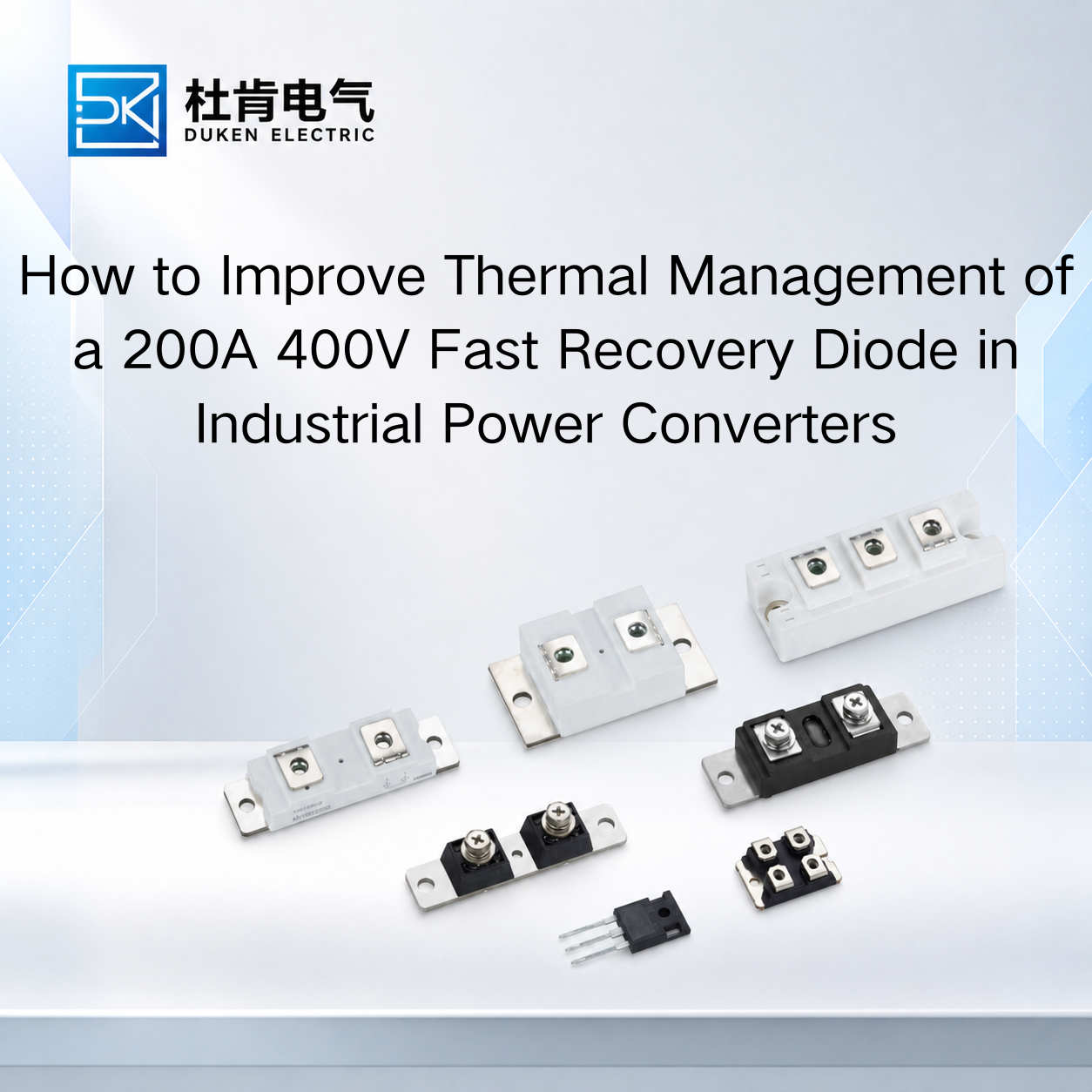
How to Improve Thermal Management of a 200A 400V Fast Recovery Diode in Industrial Power Converters
Understanding how to improve thermal management of a 200A 400V fast recovery diode is critical when the device operates in welding inverters, UPS systems, motor drives, bridge rectifiers, industrial power converters, or other high-current switching equipment. At 200A-class current levels, even a small increase in forward voltage, reverse recovery loss, contact resistance, or heat-sink temperature can significantly raise junction temperature. Effective thermal design therefore requires more than choosing a large heat sink. Engineers must evaluate semiconductor loss, package thermal resistance, mounting method, airflow, reverse recovery behavior, and the interaction between the diode and associated IGBT or MOSFET.
For industrial OEMs and procurement managers, thermal performance should be treated as part of component qualification rather than as a problem to solve after the prototype begins overheating.
Start with the Real Sources of Diode Power Loss
The first step in understanding how to improve thermal management of a 200A 400V fast recovery diode is determining how much heat the diode actually produces.
Forward conduction loss is one of the main heat sources. A simplified first-order relationship is:
Pcond ≈ VF × IF(avg)
At high current, forward voltage becomes very important. If a diode carries 150A average current during part of its operating cycle, even a relatively small difference in VF can create a significant change in heat generation.
This is why a brand Vishay equivalent glass-metal seal housing low conduction loss 200A 400V fast recovery diode should not be evaluated only by current and voltage ratings. Engineers should compare VF at relevant current and temperature conditions, because a replacement with higher forward voltage may run considerably hotter in the same assembly.
Fast recovery diodes also generate switching-related loss.
When a silicon PN diode changes from forward conduction to reverse blocking, stored charge must be removed. Reverse recovery parameters such as Qrr, trr, and peak reverse recovery current influence the energy dissipated during each switching transition.
At higher switching frequency, this loss becomes increasingly important.
A simplified system relationship is:
Psw ≈ Esw × fs
where Esw represents energy per switching event and fs represents switching frequency.
Therefore, the lowest-VF diode is not automatically the thermally best solution. A device with slightly lower forward voltage but much higher Qrr may reduce conduction loss while increasing switching stress and heat elsewhere in the converter.
Improve the Junction-to-Heat-Sink Thermal Path
Once semiconductor losses are understood, the next objective is minimizing thermal resistance between the junction and the cooling system.
A useful simplified relationship is:
Tj = Tc + P × Rth(j-c)
where Tj is junction temperature, Tc is case temperature, P is semiconductor loss, and Rth(j-c) is junction-to-case thermal resistance.
However, Rth(j-c) represents only part of the total thermal path.
In an actual industrial assembly, heat must travel from the semiconductor junction through the package, through the mounting interface, into the heat sink, and finally into the surrounding air or coolant.
This is particularly important for a 3/4″-16UNF stud type for bridge rectifier module stud mount DO-9 200A 400V fast recovery diode. Stud-mounted devices depend heavily on correct mechanical contact with the heat sink or conductive mounting structure.
The mounting surface should be clean, flat, and compatible with the device manufacturer's installation requirements. Improper mounting can increase thermal contact resistance even when the heat sink itself is adequately sized.
Correct mounting torque is equally important. Insufficient tightening can reduce thermal and electrical contact, while excessive torque can place mechanical stress on the package or stud.
For a 3/4″-16UNF stud type for bridge rectifier module stud mount DO-9 200A 400V fast recovery diode, polarity must also be checked because the stud may be electrically connected to either the anode or cathode depending on the device version.
If electrical isolation from the heat sink is required, the insulation layer must be selected carefully. A material with poor thermal conductivity can substantially increase case-to-heat-sink thermal resistance and offset the benefit of a low-Rth diode package.
Optimize Heat Sink and Airflow for Continuous Industrial Operation
Heat-sink selection should be based on real operating loss and ambient conditions rather than physical size alone.
A large aluminum heat sink may still perform poorly if airflow is restricted or if hot air recirculates inside the cabinet.
Forced-air systems should consider fan position, airflow direction, fin spacing, inlet-air temperature, and nearby heat sources such as IGBT modules, transformers, inductors, and braking resistors.
The thermal design should also account for aging.
Fans lose performance over time. Dust accumulates on heat-sink fins. Filters become blocked. Industrial cabinet temperatures may rise during summer or under higher production loads.
Therefore, a diode should not be designed to operate continuously near its absolute maximum junction temperature when the cooling system is brand new.
A reasonable thermal margin improves tolerance to real field conditions.
This is especially important for a high switching speed industrial power converter low reverse leakage current 200A 400V fast recovery diode because switching loss and leakage can both be influenced by temperature.
Reverse leakage generally increases as junction temperature rises. Although leakage current is usually much smaller than forward operating current, elevated temperature can still reduce blocking-state margin and contribute to additional device stress.
For this reason, procurement engineers should compare IR under similar voltage and temperature conditions rather than ranking products by whichever datasheet shows the smallest room-temperature number.
Reduce Thermal Stress by Controlling Reverse Recovery and Circuit Layout
Another way to improve thermal management is to reduce unnecessary switching stress before attempting to increase cooling capacity.
A high switching speed industrial power converter low reverse leakage current 200A 400V fast recovery diode should be selected with suitable Qrr and trr for the actual switching frequency and circuit topology.
If reverse recovery is excessive, the associated IGBT or MOSFET may experience a higher turn-on current peak. This can increase switching losses in both the diode and the transistor.
Circuit parasitic inductance can also contribute to voltage overshoot:
V = L × di/dt
High overshoot can increase switching stress and may require snubbers, optimized busbar layout, shorter current loops, or revised gate-drive conditions.
Thermal management therefore begins partly with electrical design.
A better diode combined with a low-inductance commutation loop may generate less heat than a nominally higher-rated device installed in a poor switching layout.
Engineers should observe the diode current, reverse-voltage waveform, and switch behavior using suitable test equipment under representative load conditions. This provides stronger evidence than relying only on trr values from unrelated datasheet test circuits.
Compare FRD, Standard Diode and SiC from a Thermal Perspective
When evaluating how to improve thermal management of a 200A 400V fast recovery diode, it is useful to compare semiconductor technologies.
A conventional silicon rectifier diode can offer strong current capability, low cost, and good surge performance. In line-frequency bridge rectification, it may be thermally efficient because reverse recovery occurs infrequently.
In a high-frequency converter, however, slower recovery can increase switching losses substantially.
A silicon fast recovery diode provides a compromise between mature high-current silicon technology and improved switching behavior. It remains practical in welding inverters, UPS systems, motor drives, industrial converters, and many legacy power platforms.
SiC Schottky diodes offer much lower minority-carrier reverse recovery. In high-frequency applications, this can reduce switching losses and decrease thermal stress on both the diode and associated transistor.
However, SiC is not automatically the best thermal solution.
At 200A-class current levels, conduction loss, package availability, cost, mounting structure, cooling design, switching frequency, and supplier availability must also be considered.
For an established industrial converter operating at moderate frequency, a well-selected silicon FRD may provide sufficient thermal margin at a lower total system cost.
Validate Thermal Performance Before Bulk Procurement
The final step is testing the candidate diode in representative equipment.
The diode should be installed using the intended mounting method, thermal interface, heat sink, airflow, and electrical circuit. Testing should reproduce realistic current, switching frequency, ambient temperature, and duty cycle.
Short bench tests can be misleading because the heat sink and surrounding components may not yet have reached thermal equilibrium.
Engineers should monitor case temperature after sustained operation and use the manufacturer's thermal data to estimate whether sufficient junction-temperature margin remains.
For second-source qualification, comparing the original and proposed diode under identical operating conditions is especially useful.
A brand Vishay equivalent glass-metal seal housing low conduction loss 200A 400V fast recovery diode should demonstrate acceptable temperature, conduction loss, recovery behavior, package compatibility, and switching performance before volume approval.
Likewise, mechanical compatibility of a stud-mounted alternative should be verified together with electrical polarity and mounting conditions.
The objective is not simply to confirm that the diode survives. It is to ensure that the complete power stage operates with enough thermal margin for long-term industrial service.
Conclusion
Knowing how to improve thermal management of a 200A 400V fast recovery diode requires combining semiconductor selection, mounting quality, heat-sink design, airflow, recovery performance, and circuit layout.
Forward voltage and Qrr determine how much heat is generated, while Rth(j-c), thermal interfaces, mounting conditions, and cooling determine how effectively that heat is removed. Stud-mounted DO-9 devices require careful attention to torque, polarity, and contact quality, while high-speed converter applications require particular attention to reverse recovery and parasitic inductance.
For OEMs, engineers, and procurement managers, the most reliable approach is to evaluate the complete diode-to-ambient thermal path and verify candidate devices under realistic operating conditions before bulk purchasing. This produces better long-term reliability than simply selecting a diode with the highest current rating or largest heat sink.
FAQ
Q1: What is the biggest source of heat in a 200A fast recovery diode?
Forward conduction loss is often significant, but reverse recovery can also contribute substantial switching-related loss in higher-frequency converters.
Q2: Does a lower Rth(j-c) always mean the diode will run cooler?
No. Thermal-interface resistance, heat-sink performance, airflow, mounting quality, and actual device losses also determine junction temperature.
Q3: Why is mounting torque important for a stud-type diode?
Correct torque helps maintain proper electrical and thermal contact. Too little can increase contact resistance, while excessive torque may mechanically stress the package.
Q4: Can changing to SiC solve a thermal problem?
It can reduce recovery-related switching losses in suitable high-frequency circuits, but total thermal performance also depends on conduction loss, package, cooling, cost, and converter design.
Q5: Should thermal testing be done before bulk procurement?
Yes. Representative testing can reveal temperature, switching, mounting, and recovery issues that cannot be determined from current and voltage ratings alone.
READ MORE:
Procurement and Qualification Guide for Qrr in 200A 400V Fast Recovery Diodes
Qrr and Thermal Reliability in 200A 400V Fast Recovery Diodes for Industrial Power Systems
How to Compare Qrr Specifications When Selecting a 200A 400V Fast Recovery Diode
How Qrr Affects Switching Loss and IGBT Stress in 200A 400V Fast Recovery Diodes
Understanding Qrr in 200A 400V Fast Recovery Diodes: What Industrial Buyers Must Know
Preventing Overheating and Extending Service Life of 200A 400V Fast Recovery Diodes
Thermal Reliability Design for 200A 400V Fast Recovery Diodes in Bridge Rectifiers
Reverse Recovery Loss and Cooling Optimization for 200A 400V Fast Recovery Diodes
Reducing Junction Temperature in 200A 400V Fast Recovery Diodes Through Package and Mounting Design