
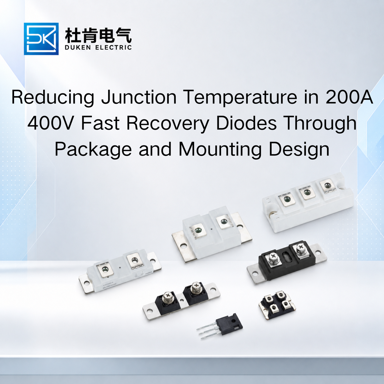
Reducing Junction Temperature in 200A 400V Fast Recovery Diodes Through Package and Mounting Design
Understanding how to improve thermal management of a 200A 400V fast recovery diode requires more than calculating semiconductor losses or selecting a larger heat sink. In high-current industrial rectifiers, welding equipment, UPS systems, motor drives, and power converters, package construction and mounting quality can strongly influence the temperature reached by the semiconductor junction. A 200A diode with suitable electrical specifications can still overheat if the mounting surface, stud connection, thermal interface, or cooling structure creates excessive thermal resistance. For OEM engineers and procurement managers, package-level thermal design should therefore be evaluated together with forward voltage, reverse recovery, leakage current, and application operating conditions when selecting or replacing a fast recovery diode.
Why Package Construction Matters at 200A Current Levels
The semiconductor junction generates heat primarily through conduction and switching-related losses. That heat must travel through the package before it can reach the external cooling system.
Conduction loss can initially be approximated by:
Pcond ≈ VF × IF(avg)
At a 200A current class, relatively small differences in forward voltage can have a meaningful effect on total heat generation. However, producing less heat is only half of the thermal-management problem. The generated heat must also leave the device efficiently.
This is why a brand Vishay equivalent glass-metal seal housing low conduction loss 200A 400V fast recovery diode should be evaluated for both electrical and mechanical construction.
Glass-metal sealed packages are commonly associated with mechanically robust power semiconductor structures and can provide effective environmental sealing when properly manufactured. For industrial buyers evaluating an equivalent product, however, a similar external housing does not prove identical internal construction or thermal performance.
Engineers should compare relevant datasheet characteristics such as VF, Rth(j-c), junction-temperature limits, recovery behavior, reverse leakage, and package dimensions.
A replacement should also be evaluated under the same current and cooling conditions as the original diode. If the proposed device has lower conduction loss but a less favorable thermal path, the expected temperature improvement may be smaller than anticipated.
Conversely, a diode with an effective package thermal path can sometimes maintain an acceptable junction temperature even when its electrical characteristics are only moderately different.
The correct selection therefore requires balancing heat generation and heat removal rather than optimizing one datasheet number independently.
Stud Mounting Can Become Part of the Thermal Path
Stud-type power diodes illustrate particularly well why mechanical installation matters.
A 3/4″-16UNF stud type for bridge rectifier module stud mount DO-9 200A 400V fast recovery diode uses its threaded mechanical connection as an important part of the physical installation and, depending on package construction, the electrical and thermal path.
The mounting surface should therefore be treated as part of the thermal system.
If the surface is contaminated, uneven, damaged, or incorrectly prepared, the effective thermal resistance between the diode and heat sink can increase. This can produce a higher case and junction temperature even though the semiconductor itself is functioning normally.
Mounting torque also matters. Engineers should use the manufacturer's specified torque rather than assuming that all physically similar stud diodes require the same value. Insufficient tightening can compromise contact, while excessive mechanical force can damage threads or stress the package.
A 3/4″-16UNF stud type for bridge rectifier module stud mount DO-9 200A 400V fast recovery diode should also be checked for polarity before installation. Depending on the specific device configuration, the stud can be electrically associated with the anode or cathode.
This matters when the heat sink or mounting plate is electrically conductive.
If electrical isolation is necessary, the insulation method introduces another thermal interface. Engineers should select insulation and interface materials according to both dielectric and thermal requirements. Solving an electrical isolation problem by introducing excessive thermal resistance can create a new overheating problem.
For procurement teams, mechanical drawings are therefore just as important as basic electrical ratings when evaluating a stud diode replacement.
Heat Sink Design Should Follow the Complete Thermal Resistance Chain
A common thermal-design mistake is selecting a heat sink from diode current alone.
The required cooling capacity depends on semiconductor loss, allowable junction temperature, ambient conditions, thermal interfaces, and the heat sink's ability to reject heat.
A simplified junction-to-case calculation is:
Tj = Tc + P × Rth(j-c)
The complete system must also consider case-to-heat-sink and heat-sink-to-ambient thermal resistance.
This becomes especially important when engineers are trying to determine how to improve thermal management of a 200A 400V fast recovery diode in an existing converter. Replacing the heat sink may help, but it should not be the first action taken without understanding where the thermal bottleneck occurs.
If the semiconductor has high conduction or recovery loss, increasing heat-sink size addresses the consequence rather than the source.
If the heat sink remains relatively cool while the diode case becomes unusually hot, the mounting interface may deserve investigation.
If the entire heat sink reaches a high temperature, airflow or heat-sink capacity may be limiting system performance.
Forced-air cooling can improve thermal performance substantially, but fan location and airflow path are important. Air should move effectively through the heat-sink fins rather than bypassing them or recirculating hot air inside the cabinet.
Industrial design should also consider long-term degradation. Dust, blocked filters, fan wear, and elevated ambient temperature can gradually reduce cooling performance. Maintaining thermal margin during initial qualification helps accommodate these real operating conditions.
Switching Speed and Reverse Recovery Also Influence Temperature
Mechanical improvements cannot fully solve overheating if excessive heat is being generated during switching.
A high switching speed industrial power converter low reverse leakage current 200A 400V fast recovery diode should have recovery characteristics appropriate for the converter's switching frequency and commutation conditions.
Silicon fast recovery diodes contain stored charge during forward conduction. When reverse voltage is applied, that charge must be removed before the diode fully establishes reverse blocking.
Qrr, trr, and reverse recovery current therefore influence switching stress.
Higher reverse recovery current can also increase the turn-on stress experienced by the associated IGBT or MOSFET. Consequently, poor diode recovery can increase losses in more than one component.
A high switching speed industrial power converter low reverse leakage current 200A 400V fast recovery diode should therefore be evaluated as part of the switching cell rather than as an isolated component.
Low reverse leakage is useful for blocking performance, but leakage values should be compared at equivalent voltage and temperature conditions. Leakage generally increases with junction temperature, making hot-state data particularly valuable in applications with high case temperatures.
Circuit layout also matters. Parasitic inductance can generate voltage overshoot according to:
V = L × di/dt
Shorter commutation loops, appropriate busbar design, suitable snubbers, and coordinated gate-drive settings can reduce unnecessary switching stress.
Improving the electrical switching environment can therefore reduce heat generation before engineers make changes to the cooling hardware.
Choosing Between Silicon FRD and SiC for Better Thermal Performance
For new designs, engineers may consider whether a silicon FRD remains the best option or whether a SiC diode would provide better thermal performance.
Standard silicon rectifier diodes are well suited to low-frequency rectification but can generate substantial recovery-related losses when used in faster switching circuits.
Silicon fast recovery diodes improve this behavior and remain widely practical where high current capability, established packaging, cost control, and moderate switching frequency are important.
SiC Schottky diodes behave differently because they have very low minority-carrier reverse recovery. This can reduce switching losses significantly in suitable high-frequency converters and can also reduce switching stress on the associated transistor.
However, SiC should not automatically be selected solely because it has better recovery characteristics.
At 200A-class current levels, engineers still need to evaluate forward conduction loss, package options, cooling architecture, surge requirements, cost, and availability. A converter originally designed around a stud-mounted silicon FRD may require mechanical or electrical changes before a SiC alternative becomes practical.
For replacement projects, a brand Vishay equivalent glass-metal seal housing low conduction loss 200A 400V fast recovery diode may therefore provide a more straightforward path when maintaining the existing mechanical and electrical architecture is a priority.
For new high-frequency designs, SiC deserves stronger consideration when reduced recovery loss provides a meaningful system-level efficiency and thermal advantage.
Conclusion
Knowing how to improve thermal management of a 200A 400V fast recovery diode requires engineers to examine the complete path from semiconductor loss generation to heat rejection.
Forward voltage, reverse recovery, and leakage determine part of the heat generated inside the device. Package thermal resistance, mounting surfaces, stud installation, interface materials, heat-sink design, and airflow determine how effectively that heat is removed.
For stud-mounted DO-9 devices, correct mechanical installation is especially important because poor contact can compromise both thermal and electrical performance. In higher-frequency converters, Qrr and switching behavior should also be optimized before simply increasing heat-sink capacity.
For OEMs and procurement teams, the strongest qualification method is to compare electrical and mechanical specifications, install candidate devices using the intended production process, and test temperature under representative current, switching, cooling, and ambient conditions. This provides a more reliable basis for long-term industrial operation than selecting components from current ratings alone.
FAQ
Q1: Why can a 200A diode overheat even when current is below its rating?
The rating depends on specified thermal and operating conditions. High VF, recovery losses, poor mounting, inadequate cooling, or elevated ambient temperature can still produce excessive junction temperature.
Q2: Does a stud-mounted diode need a thermal interface material?
That depends on the package, mounting structure, electrical isolation requirements, and manufacturer's instructions. Any interface material should be evaluated for both thermal and electrical performance.
Q3: Why should mounting torque follow the diode manufacturer's specification?
Incorrect torque can affect mechanical and thermal contact or damage the package. Similar-looking stud diodes do not necessarily have identical mounting requirements.
Q4: Does faster trr always mean lower diode temperature?
No. trr alone does not describe total loss. Qrr, reverse recovery current, VF, switching conditions, temperature, and circuit topology must also be considered.
Q5: Is SiC always thermally better than a silicon fast recovery diode?
Not in every system. SiC can significantly reduce recovery-related switching losses, but conduction loss, package compatibility, operating frequency, cooling, surge requirements, and cost also influence the best choice.
READ MORE:
Procurement and Qualification Guide for Qrr in 200A 400V Fast Recovery Diodes
Qrr and Thermal Reliability in 200A 400V Fast Recovery Diodes for Industrial Power Systems
How to Compare Qrr Specifications When Selecting a 200A 400V Fast Recovery Diode
How Qrr Affects Switching Loss and IGBT Stress in 200A 400V Fast Recovery Diodes
Understanding Qrr in 200A 400V Fast Recovery Diodes: What Industrial Buyers Must Know
Preventing Overheating and Extending Service Life of 200A 400V Fast Recovery Diodes
Thermal Reliability Design for 200A 400V Fast Recovery Diodes in Bridge Rectifiers
Reverse Recovery Loss and Cooling Optimization for 200A 400V Fast Recovery Diodes
How to Improve Thermal Management of a 200A 400V Fast Recovery Diode in Industrial Power Converters