
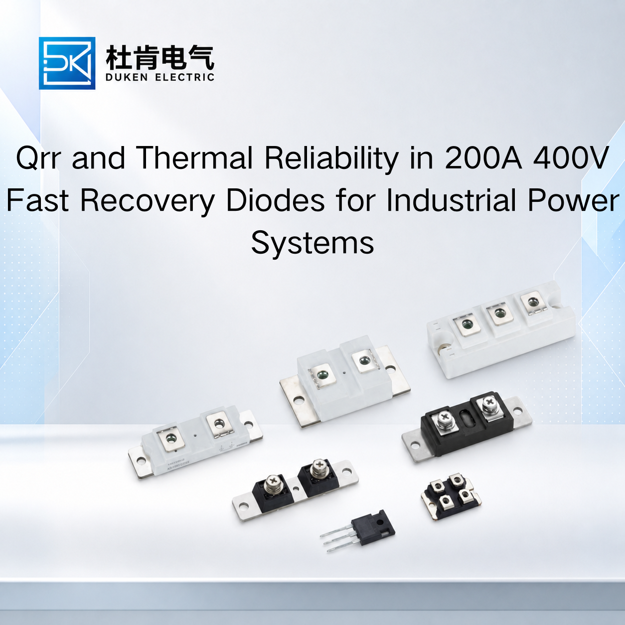
Qrr and Thermal Reliability in 200A 400V Fast Recovery Diodes for Industrial Power Systems
Understanding Qrr in 200A 400V Fast Recovery Diodes: What Buyers Must Know is not limited to switching speed. Reverse recovery charge can also influence semiconductor temperature, IGBT stress, cooling requirements, and long-term converter reliability. In welding inverters, UPS systems, motor drives, industrial DC power supplies, and high-current converters, the diode may experience millions of switching events during normal service. A device with unsuitable recovery behavior can generate additional loss during every commutation cycle. For OEMs and procurement managers, evaluating Qrr together with forward voltage, reverse leakage, junction temperature, thermal resistance, package construction, and operating frequency provides a much stronger basis for component selection than comparing 200A and 400V ratings alone.
How Qrr Becomes a Thermal Reliability Issue
When a silicon fast recovery diode conducts forward current, minority carriers are stored within the semiconductor structure. After the circuit reverses the voltage across the diode, these carriers must be removed before normal reverse blocking is established.
The resulting reverse recovery current represents an additional switching event that produces electrical and thermal stress.
Qrr describes the charge involved in this recovery process. Although it is often discussed as a switching-performance parameter, its practical influence extends directly to thermal design.
A diode with excessive recovery charge can contribute to higher switching energy. In a converter operating at substantial switching frequency, the energy associated with each event accumulates:
Psw ≈ Esw × fs
The diode itself can dissipate additional energy, while the IGBT or MOSFET performing the commutation may also experience higher turn-on loss because it must temporarily carry recovery current.
This means the thermal consequences of Qrr can appear in more than one semiconductor.
For buyers, this is particularly relevant when replacing an established component. A candidate may have the same voltage, current, and package ratings but cause the IGBT temperature to rise because its recovery characteristics differ from those of the original diode.
This system interaction is a critical part of Understanding Qrr in 200A 400V Fast Recovery Diodes: What Buyers Must Know. Qualification should therefore include the surrounding switching circuit rather than measuring only the diode case temperature.
Balancing Low Conduction Loss with Qrr and Junction Temperature
Conduction loss remains another major source of heat in high-current diodes.
A useful first-order relationship is:
Pcond ≈ VF × IF(avg)
At 200A-class currents, even a moderate difference in forward voltage can influence total heat dissipation. This is why buyers frequently search for a brand Vishay equivalent glass-metal seal housing low conduction loss 200A 400V fast recovery diode when replacing established industrial components.
However, lower VF should not be evaluated independently from recovery behavior.
In a moderate-frequency application with long conduction periods, conduction loss may represent a substantial portion of total diode loss. In this situation, lower VF can provide an important thermal advantage.
As switching frequency increases, Qrr becomes more significant. Selecting a diode with lower conduction loss but substantially greater reverse recovery charge may simply move losses from one part of the switching cycle to another.
Junction temperature further complicates the comparison because semiconductor characteristics change with temperature. Reverse leakage generally increases at elevated temperature, while recovery behavior can also differ from room-temperature measurements.
For a brand Vishay equivalent glass-metal seal housing low conduction loss 200A 400V fast recovery diode, engineers should therefore compare VF, Qrr, trr, leakage, Rth(j-c), and applicable Tj limits under relevant conditions.
The thermal relationship can be simplified as:
Tj = Tc + P × Rth(j-c)
In practice, case-to-heat-sink and heat-sink-to-ambient thermal resistance must also be considered.
This is why a low-loss diode can still operate too hot if its mounting interface or cooling system is inadequate.
Stud-Mounted DO-9 Diodes: Electrical and Thermal Qualification
Package design becomes especially important in high-current industrial rectifiers.
A 3/4″-16UNF stud type for bridge rectifier module stud mount DO-9 200A 400V fast recovery diode may be selected because it offers the mechanical format required for an existing rectifier assembly.
But matching the thread is only the beginning.
The stud connection can form an important part of the thermal path from the semiconductor package into the heat sink. Mounting-surface condition and installation requirements can therefore influence junction temperature.
The manufacturer's specified mounting conditions should be followed. Excessive or insufficient torque can compromise the mechanical assembly, so torque values should not be copied automatically from a physically similar diode.
Polarity must also be confirmed. Depending on device configuration, the stud may correspond to the anode or cathode. This is particularly important when the mounting structure is electrically conductive.
A 3/4″-16UNF stud type for bridge rectifier module stud mount DO-9 200A 400V fast recovery diode used in a relatively low-frequency bridge may place greater emphasis on VF, surge-current capability, thermal resistance, and mechanical robustness than on extremely low Qrr.
If the same package is used in a higher-frequency commutation circuit, recovery behavior becomes more important.
This difference demonstrates why purchasing by model dimensions alone is risky. Application frequency and circuit function determine which parameters deserve priority.
Qrr Requirements in High-Speed Industrial Power Converters
For a high switching speed industrial power converter low reverse leakage current 200A 400V fast recovery diode, Qrr becomes closely linked to switching efficiency and device stress.
When the associated IGBT turns on, it may need to conduct diode reverse recovery current in addition to the load current. A larger recovery event can increase instantaneous transistor current and switching energy.
Circuit parasitic inductance can make the situation more severe:
V = L × di/dt
Rapid changes in recovery current can interact with busbar and connection inductance to generate voltage overshoot and ringing.
This does not mean that the diode alone determines switching quality. Gate resistance, IGBT switching characteristics, snubber networks, busbar geometry, and circuit inductance all influence the final waveform.
For a high switching speed industrial power converter low reverse leakage current 200A 400V fast recovery diode, application-level testing should therefore evaluate the diode and transistor as a commutation pair.
Engineers can compare recovery-current waveforms, transistor turn-on behavior, overshoot, case temperature, and heat-sink temperature under representative operating conditions.
This approach is especially useful when approving a second source. If the original and replacement devices are tested in the same converter, engineers can identify whether changes in Qrr produce meaningful thermal or electrical differences.
Low reverse leakage is also valuable, but buyers should compare leakage at similar voltage and temperature conditions. A very low leakage specification at room temperature cannot replace an evaluation of hot-state performance.
Silicon FRD or SiC: When Lower Recovery Charge Justifies a Technology Change
The comparison between silicon FRDs and SiC Schottky diodes illustrates how strongly recovery behavior can influence converter design.
A standard silicon rectifier diode remains suitable for many low-frequency rectification applications. Its priorities may include low forward loss, surge capability, cost, and robust packaging rather than very fast recovery.
A silicon FRD provides improved recovery behavior and is widely used in switched industrial equipment where standard rectifier diodes would generate excessive commutation losses.
SiC Schottky diodes go further by providing very low minority-carrier reverse recovery. In high-frequency converters, this can reduce switching loss and the turn-on stress imposed on associated MOSFETs or IGBTs.
However, lower recovery loss does not automatically make SiC the best choice for every 200A application.
High-current systems must also consider forward conduction characteristics, surge requirements, package availability, heat-sink structure, mechanical compatibility, supply continuity, and component cost.
For an existing industrial platform designed around a stud-mounted silicon FRD, replacing the diode with another suitably qualified silicon FRD may require fewer system changes.
For a new high-frequency converter where switching loss significantly influences efficiency and power density, SiC may provide greater system-level value.
The decision should therefore be based on total converter performance rather than Qrr alone.
Conclusion
Understanding Qrr in 200A 400V Fast Recovery Diodes: What Buyers Must Know requires connecting reverse recovery behavior with thermal reliability.
Qrr can influence diode switching loss, IGBT turn-on energy, voltage overshoot, junction temperature, and ultimately the thermal margin available to the complete converter. However, lower Qrr should not be pursued independently from VF, leakage current, trr, thermal resistance, surge capability, and mechanical requirements.
For OEMs and industrial buyers, datasheet screening should be followed by representative application testing. Comparing original and replacement devices under the same current, switching frequency, cooling, and ambient conditions provides stronger evidence than comparing isolated specification values.
The most reliable 200A 400V fast recovery diode is therefore not necessarily the one with the lowest Qrr. It is the device that provides an appropriate balance of conduction, recovery, blocking, thermal, and mechanical characteristics for the intended industrial power system.
FAQ
Q1: Can high Qrr increase diode operating temperature?
Yes. Reverse recovery contributes to switching-related energy loss, and repeated recovery events can increase average power dissipation as switching frequency rises.
Q2: Can Qrr affect IGBT reliability?
Yes. The IGBT may carry additional diode recovery current during turn-on, increasing switching energy and thermal stress.
Q3: Should VF or Qrr receive higher priority?
It depends on the application. Lower-frequency, high-duty conduction applications may emphasize VF, while higher-frequency converters usually place greater importance on recovery characteristics.
Q4: Does package mounting influence Qrr?
Mounting does not directly define Qrr, but poor thermal contact can increase junction temperature, and temperature can influence semiconductor recovery behavior.
Q5: Is SiC always better when Qrr is important?
No. SiC can provide major recovery advantages, but conduction characteristics, surge requirements, package compatibility, cooling, cost, and system architecture must also be evaluated.
READ MORE:
Procurement and Qualification Guide for Qrr in 200A 400V Fast Recovery Diodes
How to Compare Qrr Specifications When Selecting a 200A 400V Fast Recovery Diode
How Qrr Affects Switching Loss and IGBT Stress in 200A 400V Fast Recovery Diodes
Understanding Qrr in 200A 400V Fast Recovery Diodes: What Industrial Buyers Must Know
Preventing Overheating and Extending Service Life of 200A 400V Fast Recovery Diodes
Thermal Reliability Design for 200A 400V Fast Recovery Diodes in Bridge Rectifiers
Reverse Recovery Loss and Cooling Optimization for 200A 400V Fast Recovery Diodes
Reducing Junction Temperature in 200A 400V Fast Recovery Diodes Through Package and Mounting Design
How to Improve Thermal Management of a 200A 400V Fast Recovery Diode in Industrial Power Converters