
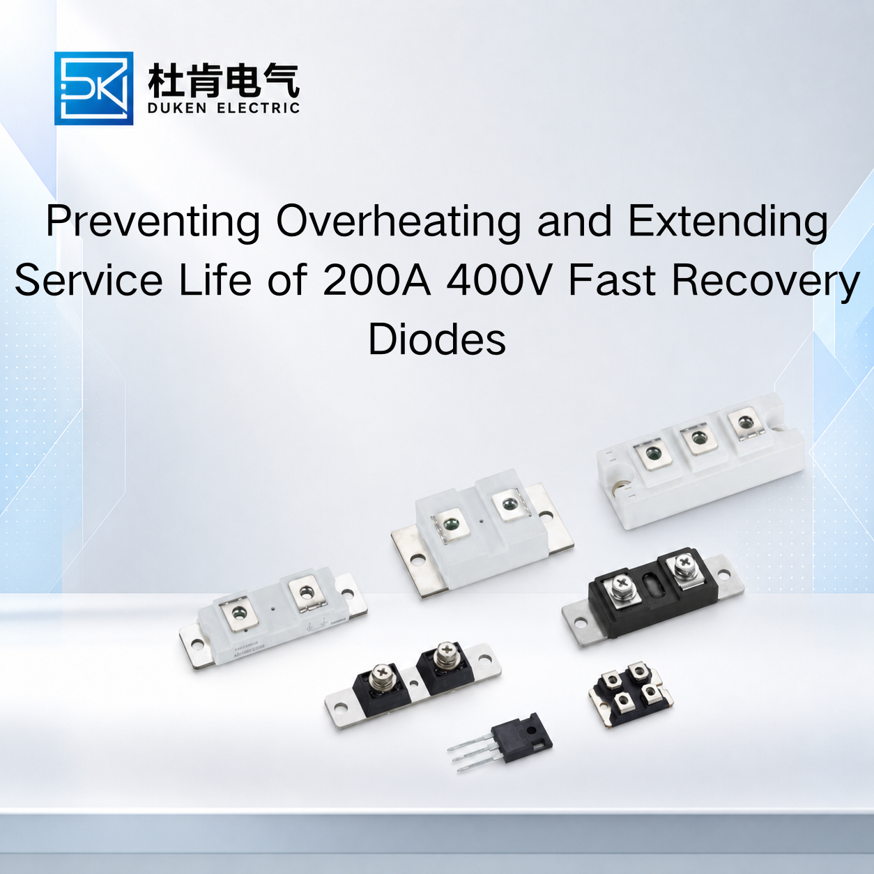
Preventing Overheating and Extending Service Life of 200A 400V Fast Recovery Diodes
For industrial power equipment, understanding how to improve thermal management of a 200A 400V fast recovery diode is closely connected with long-term reliability. Excessive junction temperature does not always cause immediate semiconductor failure. Instead, repeated operation with insufficient thermal margin can increase electrical stress, accelerate degradation of interfaces, and reduce the reliability of the complete rectifier assembly. This matters in welding machines, industrial power converters, UPS systems, motor drives, battery equipment, and bridge rectifiers where high-current diodes may operate for thousands of hours. Engineers and procurement managers should therefore consider conduction loss, reverse recovery, mounting quality, cooling-system degradation, and operating environment together when qualifying a 200A FRD.
Control Junction Temperature Instead of Focusing Only on Heat-Sink Temperature
One of the most common mistakes in thermal evaluation is assuming that an acceptable heat-sink temperature automatically means the semiconductor junction is operating safely.
The heat sink is only one point in the thermal path. Heat originates inside the semiconductor junction, moves through the package, crosses the mechanical or thermal interface, enters the heat sink, and finally transfers into the surrounding environment.
A simplified junction-to-case relationship is:
Tj = Tc + P × Rth(j-c)
Actual system analysis must also include the thermal resistance beyond the case.
The amount of heat generated depends partly on forward conduction loss. A first-order estimate is:
Pcond ≈ VF × IF(avg)
At 200A-class currents, forward voltage is therefore a major selection parameter. A small increase in VF can translate into additional power dissipation that the cooling system must continuously remove.
This is why a brand Vishay equivalent glass-metal seal housing low conduction loss 200A 400V fast recovery diode should be evaluated at relevant current and temperature conditions rather than by comparing only maximum current ratings.
When qualifying an equivalent device, engineers should compare the original and replacement under the same current waveform, cooling method, and ambient conditions. The comparison should include VF, thermal resistance, recovery behavior, leakage current, package dimensions, and applicable junction-temperature limits.
A lower maximum Rth(j-c) can be useful, but it does not compensate automatically for substantially higher semiconductor losses.
The practical objective is to maintain adequate junction-temperature margin during realistic worst-case operation rather than designing the device to remain just below its absolute thermal limit.
Prevent Mounting Problems in High-Current Stud Diodes
Mechanical installation is particularly important for stud-mounted power semiconductors because the mounting structure can form a major part of both the electrical and thermal path.
A 3/4″-16UNF stud type for bridge rectifier module stud mount DO-9 200A 400V fast recovery diode should be installed on a mechanically suitable surface according to the manufacturer's mounting requirements.
Surface quality matters. Contamination, oxidation, scratches, uneven mounting areas, or other defects can interfere with thermal transfer. In an industrial bridge assembly carrying substantial current, additional contact resistance can also create localized heating.
Mounting torque should follow the specification for the particular diode. Similar external packages do not necessarily require identical torque.
Too little tightening can produce inadequate contact. Excessive tightening can damage the stud, threads, or semiconductor package. Using a larger wrench to solve an apparent overheating problem is therefore not a valid thermal-management strategy.
Polarity must also be confirmed before installation. A 3/4″-16UNF stud type for bridge rectifier module stud mount DO-9 200A 400V fast recovery diode may be supplied with different stud polarity depending on the product configuration.
This is especially important in bridge assemblies where the heat sink or mounting plate is electrically conductive.
Electrical insulation can create another design trade-off. If the diode must be isolated from the heat sink, the insulating interface should provide the required dielectric performance without creating excessive thermal resistance.
Mechanical drawings and mounting specifications should therefore be included in replacement qualification rather than reviewed only after samples arrive.
For purchasing teams, a mechanically incompatible equivalent can create additional machining, busbar, insulation, or assembly costs even when the semiconductor itself is electrically suitable.
High Switching Speed Requires Careful Reverse Recovery Management
In switching power converters, cooling improvements alone may not solve the underlying source of excessive temperature.
A high switching speed industrial power converter low reverse leakage current 200A 400V fast recovery diode experiences both conduction and commutation losses. When the silicon PN diode transitions from forward conduction to reverse blocking, stored charge must be removed.
Reverse recovery behavior is commonly characterized by Qrr, trr, and reverse recovery current.
These characteristics become increasingly important as switching frequency rises because recovery occurs repeatedly. The approximate relationship:
Psw ≈ Esw × fs
shows why even a modest amount of switching energy can become significant at higher frequency.
Reverse recovery also affects the associated transistor. When an IGBT or MOSFET turns on while the diode is recovering, the switch may need to conduct additional recovery current. This increases switching stress and can raise transistor temperature.
A high switching speed industrial power converter low reverse leakage current 200A 400V fast recovery diode should therefore be evaluated together with its switching device.
Engineers should avoid comparing trr numbers without checking the datasheet test conditions. Forward current, di/dt, reverse voltage, and temperature can all influence the measured recovery behavior.
Reverse leakage should be treated similarly. Leakage current normally increases with temperature, so a very low room-temperature IR specification does not provide a complete picture of hot operating performance.
For high-reliability applications, hot-state leakage and recovery behavior can provide useful additional information during sample qualification.
Cooling Systems Must Be Designed for Aging and Industrial Environments
Understanding how to improve thermal management of a 200A 400V fast recovery diode also requires considering what happens to the cooling system after several years of service.
A new fan, clean filter, and uncontaminated heat sink represent ideal conditions. Industrial equipment rarely remains in that state.
Dust accumulation can reduce airflow through heat-sink fins. Filters can become blocked. Fan bearings wear, and airflow can gradually decline. Nearby transformers, inductors, and power modules can raise local cabinet temperature.
These changes reduce thermal margin without changing the diode itself.
OEMs should therefore design cooling systems with realistic environmental conditions in mind. Equipment intended for continuous industrial operation should not depend on perfect airflow to prevent the diode from approaching its maximum junction temperature.
Temperature monitoring can also help in critical equipment. Monitoring heat-sink or case temperature does not directly measure junction temperature, but it can identify abnormal thermal trends when the relationship between measured temperature and operating conditions has been characterized during development.
Maintenance practices matter as well. Cleaning heat sinks, inspecting fans, checking electrical connections, and verifying mounting integrity can prevent a gradual cooling problem from being misdiagnosed as semiconductor quality deterioration.
Thermal reliability is therefore a combination of semiconductor selection, equipment design, and maintenance strategy.
Selecting Silicon FRD, Standard Diode or SiC for Long-Term Reliability
The most suitable diode technology depends on how the equipment operates.
A conventional silicon rectifier diode can provide mature, cost-effective high-current rectification where switching frequency is low. In such applications, ultra-fast recovery may provide little system-level advantage.
Silicon FRDs are more appropriate when faster commutation is required. They provide a practical balance between high-current capability, recovery performance, established industrial packaging, and cost.
SiC Schottky diodes can significantly reduce reverse-recovery-related switching losses in high-frequency converters because they have very low minority-carrier stored charge. This can reduce both diode loss and transistor turn-on stress.
However, technology selection should consider the complete power stage.
A brand Vishay equivalent glass-metal seal housing low conduction loss 200A 400V fast recovery diode can remain an attractive option for an established industrial converter where mechanical compatibility, existing cooling hardware, current capability, and replacement cost are important.
A new high-frequency design may benefit more from SiC if switching losses represent a substantial share of total thermal dissipation.
Neither decision should be based solely on whether one semiconductor technology is newer. The correct choice is the device that provides suitable electrical performance, thermal margin, mechanical compatibility, availability, and total system cost for the intended operating conditions.
Conclusion
A long-term strategy for how to improve thermal management of a 200A 400V fast recovery diode should address both heat generation and heat removal.
Forward voltage affects conduction loss, while reverse recovery influences switching loss and stress on associated IGBTs or MOSFETs. Package thermal resistance, stud mounting, electrical isolation, heat-sink design, airflow, ambient temperature, and cooling-system aging determine whether those losses can be removed safely.
For industrial buyers, thermal qualification should therefore extend beyond the datasheet. Candidate diodes should be tested using representative current, switching frequency, mounting, cooling, and ambient conditions. For second-source products, comparison with the established diode under identical equipment conditions provides particularly useful evidence.
A 200A 400V FRD that operates with sufficient thermal margin can deliver much more predictable industrial reliability than a device selected only because it offers a higher headline current rating, shorter recovery time, or lower purchase price.
FAQ
Q1: What causes a 200A fast recovery diode to overheat?
Common causes include high forward loss, reverse recovery loss, poor thermal contact, inadequate heat-sink capacity, restricted airflow, elevated ambient temperature, and unsuitable operating conditions.
Q2: Can a diode be overheating even if the heat sink does not appear extremely hot?
Yes. High thermal resistance between the diode and heat sink can create a significant junction or case temperature rise while the heat sink remains comparatively cooler.
Q3: Why should hot-state leakage be considered?
Reverse leakage generally increases with temperature. Elevated-temperature measurements can therefore provide additional information about blocking behavior under realistic operating conditions.
Q4: How can cooling-system aging affect diode reliability?
Dust, blocked filters, fan degradation, and increased cabinet temperature can reduce heat-removal capability and raise semiconductor junction temperature over time.
Q5: Is SiC always the best choice for reducing diode temperature?
No. SiC can provide major switching-loss advantages in high-frequency applications, but forward loss, package compatibility, surge requirements, cost, cooling architecture, and operating frequency must also be evaluated.
READ MORE:
Procurement and Qualification Guide for Qrr in 200A 400V Fast Recovery Diodes
Qrr and Thermal Reliability in 200A 400V Fast Recovery Diodes for Industrial Power Systems
How to Compare Qrr Specifications When Selecting a 200A 400V Fast Recovery Diode
How Qrr Affects Switching Loss and IGBT Stress in 200A 400V Fast Recovery Diodes
Understanding Qrr in 200A 400V Fast Recovery Diodes: What Industrial Buyers Must Know
Thermal Reliability Design for 200A 400V Fast Recovery Diodes in Bridge Rectifiers
Reverse Recovery Loss and Cooling Optimization for 200A 400V Fast Recovery Diodes
Reducing Junction Temperature in 200A 400V Fast Recovery Diodes Through Package and Mounting Design
How to Improve Thermal Management of a 200A 400V Fast Recovery Diode in Industrial Power Converters