
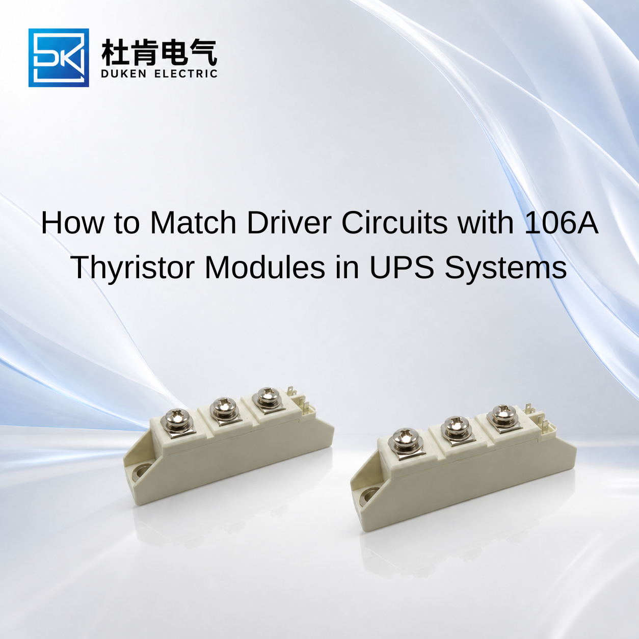
How to Match Driver Circuits with 106A Thyristor Modules in UPS Systems
Selecting Compatible driver circuits and controllers for thyristor modules is a critical part of designing or upgrading an industrial UPS power stage. A 106A SCR module may provide sufficient current, blocking voltage, and surge capability, yet still operate unreliably if the controller cannot deliver appropriate gate current or if firing pulses are poorly synchronized with the AC waveform. For UPS manufacturers and maintenance engineers, module and driver compatibility should therefore be evaluated as one system. Gate characteristics, phase-angle control, isolation, transient protection, thermal behavior, and fault response all influence whether a replacement thyristor performs reliably after installation.
Why the Gate Driver Matters in a 106A Thyristor Module
A conventional SCR is a latching semiconductor. When the device is forward biased, an appropriate gate pulse initiates conduction. After the SCR has latched, the gate no longer provides continuous control over the main current. The thyristor remains conducting until the current falls below its holding-current requirement.
This is fundamentally different from an IGBT or MOSFET, where the gate controls both switching on and switching off. As a result, SCR driver circuits should not be evaluated using the same criteria as high-frequency transistor gate drivers.
Two important SCR datasheet parameters are gate trigger current IGT and gate trigger voltage VGT. These indicate the gate conditions required to initiate conduction under specified test conditions.
A reliable controller should provide sufficient triggering margin rather than operating exactly at the published threshold. Temperature, manufacturing variation, wiring impedance, pulse-transformer characteristics, and electrical noise can all influence the effective gate signal.
This becomes particularly important when selecting Compatible driver circuits and controllers for thyristor modules from a different manufacturer. Two 106A modules with similar IT(AV) and VDRM/VRRM ratings may have different gate characteristics.
For a replacement project, engineers should therefore compare IGT, VGT, gate power limits, gate-cathode configuration, terminal arrangement, and recommended triggering conditions before approving the new module.
Pulse timing also matters. In phase-angle control, the controller determines when the SCR is triggered during each applicable AC half-cycle. Changing the firing angle changes the average power delivered through the controlled circuit.
Reliable synchronization with the AC supply is therefore essential in controlled UPS rectifier and AC power-control functions.
Surge-Protection Low Forward-Voltage Phase-Angle-Control 106A Thyristor Module for UPS Systems
A surge-protection low forward-voltage phase-angle-control 106A thyristor module for ups systems places several requirements on both the semiconductor and its controller.
Low on-state or forward voltage is valuable because the voltage drop across the conducting SCR contributes directly to power dissipation. A simplified estimate is:
Pcond ≈ VT × IT(avg)
At high current, even modest differences in VT can influence semiconductor loss and heat-sink temperature. For UPS equipment expected to operate continuously, conduction loss should therefore be considered alongside the nominal current rating.
Phase-angle control introduces another requirement. The controller must generate appropriately timed gate pulses according to the required output. In a controlled rectifier, changing firing angle changes the average DC output. In an AC power-control circuit, it changes the portion of the waveform delivered to the load.
A surge-protection low forward-voltage phase-angle-control 106A thyristor module for ups systems should also be coordinated with circuit-level surge protection.
ITSM describes specified non-repetitive surge on-state current capability, while I²t can support coordination with fast-acting semiconductor protection. These parameters are not substitutes for normal current ratings.
The driver itself does not eliminate surge-current risk. Protection may involve appropriately selected semiconductor fuses, transient suppression, snubber networks, and system-level fault detection depending on the circuit.
dv/dt should also be reviewed. Rapid voltage change while the SCR is blocking can create displacement current through internal capacitance:
i = C × dv/dt
Adequate device capability, appropriate gate design, and transient control help reduce the risk of unintended triggering.
For procurement teams, this means “compatible controller” should include both normal firing performance and stable behavior under realistic UPS transient conditions.
A46-Version Full-Module Thermal-Cycle-Resistant 106A Thyristor Module for UPS Systems
Electrical compatibility is only part of long-term module qualification. UPS equipment can experience repeated temperature changes as load rises and falls, cooling fans change operating conditions, or the system moves between normal operation, charging, bypass, and standby states.
An A46-version full-module thermal-cycle-resistant 106A thyristor module for ups systems should therefore be evaluated not only for static current capability but also for the thermal environment of the complete application.
Thermal cycling can place repeated mechanical stress on semiconductor assemblies because different internal materials expand and contract at different rates. Over long operating periods, the reliability of interfaces and connections becomes important.
The gate controller indirectly influences these conditions because poor or inconsistent triggering can create abnormal conduction behavior. If devices in a multi-SCR power stage do not fire as intended, electrical loading and resulting temperature distribution may differ from the original design.
For an A46-version full-module thermal-cycle-resistant 106A thyristor module for ups systems, buyers should request the relevant manufacturer's technical information rather than assuming that an A46 designation alone guarantees a particular lifetime or test condition. Version names can be manufacturer-specific.
Application qualification should reproduce representative UPS operating cycles where practical. Engineers can monitor case temperature and electrical behavior under sustained load, startup, bypass transitions, and other relevant operating modes.
The objective is not simply to confirm that the module switches. It is to determine whether the SCR and controller continue to operate with adequate electrical and thermal margin throughout the expected duty cycle.
Screw-Mount Certified Low Rth(j-c) 106A Thyristor Module for UPS Systems
Thermal resistance is another important parameter when comparing replacement SCR modules.
A screw-mount certified low Rth(j-c) 106A thyristor module for ups systems may provide an attractive option where the UPS design requires efficient heat transfer into an existing heat sink.
Rth(j-c) represents thermal resistance from semiconductor junction to case. Lower thermal resistance can reduce the junction-temperature rise for a given level of semiconductor loss, although the complete thermal system must still be considered.
A simplified relationship is:
Tj = Tc + P × Rth(j-c)
The actual junction-to-ambient path also includes the thermal interface, heat sink, airflow, and surrounding temperature.
Screw mounting introduces practical mechanical requirements. The module must sit correctly against the cooling surface, and mounting procedures should follow the manufacturer's specified conditions. Excessive or uneven mechanical loading should not be used as a substitute for proper thermal-interface preparation.
For a screw-mount certified low Rth(j-c) 106A thyristor module for ups systems, procurement teams should also verify what “certified” specifically means. Certification claims should be supported by relevant supplier documentation rather than assumed from a product title.
Low Rth(j-c) alone also does not establish electrical compatibility. The module must still match the controller's IGT/VGT requirements, internal topology, blocking voltage, surge capability, and terminal arrangement.
This is particularly important in replacement projects where buyers want a mechanically convenient module without redesigning the control board.
Choosing Between SCR Controllers, IGBT Drivers and Related Power Devices
Understanding semiconductor differences helps prevent incorrect controller selection.
An SCR gate controller is designed primarily to initiate conduction at the required point in the waveform. In phase-controlled circuits, accurate timing is a central function. Once the SCR has latched, the gate does not normally turn it off.
An IGBT gate driver performs a different job. It must actively command repeated turn-on and turn-off, often at kilohertz-level switching frequencies. Isolation, gate voltage, switching speed, dead time, desaturation or other protection functions may form part of an IGBT driver architecture.
A MOSFET driver likewise supports active high-frequency switching but operates according to MOSFET gate-charge and voltage requirements rather than SCR trigger-current characteristics.
A rectifier diode requires no gate driver at all. It conducts according to circuit polarity, making it appropriate for uncontrolled rectification but unsuitable where phase-angle control is required.
Therefore, changing from a 106A SCR module to an IGBT, MOSFET, or diode is not simply a component substitution. It can fundamentally change the controller and power-stage architecture.
For existing UPS systems based on line-frequency phase control, maintaining the SCR topology and qualifying a compatible driver/module combination can often provide the most practical route.
For new designs requiring high-frequency PWM and active turn-off, IGBT technology may be more appropriate, but the complete converter should be engineered around that switching method.
Conclusion
Selecting Compatible driver circuits and controllers for thyristor modules requires more than confirming that a controller can generate a gate pulse.
For a 106A UPS thyristor module, engineers should evaluate IGT, VGT, firing timing, internal topology, blocking voltage, VT, ITSM, I²t, dv/dt, thermal resistance, and terminal configuration together. The driver should provide reliable trigger margin across realistic temperature and operating conditions while remaining coordinated with the UPS protection system.
Thermal-cycle-resistant and low-Rth(j-c) modules can provide useful reliability advantages, but those features do not replace electrical compatibility. Likewise, low forward voltage and strong surge capability provide limited value if the gate controller cannot trigger the SCR consistently.
For industrial UPS manufacturers and procurement teams, the most reliable approach is to qualify the thyristor and controller as a complete functional system. This reduces replacement risk and provides a stronger technical foundation for long-term production, maintenance, and second-source sourcing.
FAQ
Q1: Can the same thyristor controller drive every 106A SCR module?
No. IGT, VGT, gate configuration, terminal arrangement, and recommended triggering conditions can vary between devices.
Q2: Why is low on-state voltage important in a UPS thyristor?
Lower VT can reduce conduction loss at high current, helping reduce semiconductor heat generation when other operating conditions are comparable.
Q3: Does a low Rth(j-c) module require a smaller heat sink?
Not necessarily. Complete cooling requirements depend on power loss, interface resistance, heat-sink performance, airflow, and ambient temperature.
Q4: Can an IGBT gate driver be used directly with an SCR?
Generally no. SCRs and IGBTs have fundamentally different gate-control requirements and switching behavior.
Q5: What should buyers check when replacing a UPS thyristor module?
Compare circuit topology, IT(AV), VDRM/VRRM, VT, IGT/VGT, ITSM, I²t, dv/dt, di/dt, Rth(j-c), dimensions, terminals, mounting, and controller compatibility.
READ MORE:
Procurement Guide to Low-Forward-Voltage 200A 400V Fast Recovery Diodes for Industrial Drives
Replacement Guide for Low-VF 200A 400V Fast Recovery Diodes in Industrial Inverters
Thermal Design Strategies for Low-VF 200A 400V Fast Recovery Diodes in Motor Drives
Low Qrr vs Low Forward Voltage: Selecting a 200A 400V Fast Recovery Diode for Frequency Inverters
Why Low Forward Voltage Matters in 200A 400V Fast Recovery Diodes
Controller Selection and Procurement Guide for 106A Thyristor Modules in UPS Systems
Selecting a Replacement 106A Thyristor Module Without Redesigning the UPS Controller
Thermal-Cycle Reliability and Driver Matching for 106A Thyristor Modules in UPS Systems
Phase-Angle Controller Design for 106A Thyristor Modules in Industrial UPS Systems