
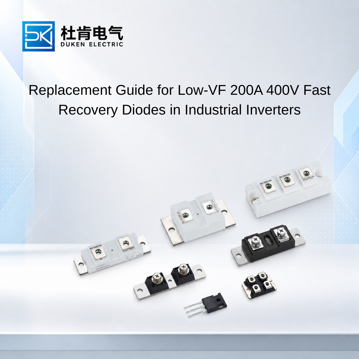
Replacement Guide for Low-VF 200A 400V Fast Recovery Diodes in Industrial Inverters
For maintenance teams and OEM engineers, 200A 400V Fast Recovery Diodes with Low Forward Voltage Drop: Benefits & Uses become especially important when an existing inverter diode is obsolete, unavailable, or causing excessive thermal loss. Finding a replacement is not simply a matter of matching “200A” and “400V.” Forward voltage, reverse-recovery charge, recovery time, surge capability, thermal resistance, package construction, polarity, and cooling conditions can all determine whether a replacement works reliably. For industrial frequency inverters and motor drives, the safest approach is to evaluate the diode together with the switching device and actual operating environment.
Why 200A and 400V Ratings Are Not Enough for Replacement Selection
A replacement search often starts with IF(AV) and VRRM. These ratings establish an important baseline, but neither one provides enough information to confirm equivalence.
The 200A current rating must be interpreted according to the conditions stated in the datasheet. Case temperature, waveform, conduction conditions, and cooling can influence the applicable current capability. Two diodes advertised as 200A devices may therefore perform differently in the same heat-sink assembly.
The same principle applies to the 400V reverse-voltage rating. Engineers need to determine the maximum reverse voltage that actually appears across the diode, including switching transients.
Inductance in busbars, wiring, motors, and other circuit elements can generate voltage during rapid current changes:
V = L × di/dt
Consequently, a circuit with a nominal voltage substantially below 400V can still produce transient peaks that deserve attention. The replacement VRRM should be selected according to measured or properly calculated circuit stress with suitable engineering margin.
Forward voltage VF is another essential replacement parameter. Conduction loss can be approximated as:
Pcond ≈ VF × IF(avg)
This explains one of the practical 200A 400V Fast Recovery Diodes with Low Forward Voltage Drop: Benefits & Uses: reducing VF can reduce heat generation when the device carries high current.
However, comparing maximum VF values from two datasheets without examining current and temperature conditions can be misleading. Engineers should compare curves or specifications under similar test conditions wherever possible.
Replacing a Dual Diode Low Forward Voltage Drop Stud Mount DO-9 200A 400V Fast Recovery Diode
Package compatibility becomes particularly important when replacing a dual diode low forward voltage drop stud mount DO-9 200A 400V fast recovery diode.
Stud-mounted devices are mechanically simple, but several details can prevent direct replacement. Stud dimensions, polarity, terminal position, mounting interface, and package height can affect installation. If an existing busbar or heat sink is designed around one specific package, even a small mechanical difference can require modification.
Electrical configuration deserves even more attention.
If a device is described as a dual diode, the internal arrangement should be confirmed from its circuit diagram. Common-anode, common-cathode, series-connected, and other configurations cannot be treated as interchangeable simply because the external package looks similar.
A replacement dual diode low forward voltage drop stud mount DO-9 200A 400V fast recovery diode should therefore be checked for VRRM, IF(AV), VF, IFSM, Qrr, trr, Rth(j-c), junction-temperature limits, polarity, and physical dimensions.
IFSM is useful when the equipment can experience short-duration current events. It describes specified non-repetitive surge-current capability rather than continuous current.
Thermal resistance also deserves attention because a mechanically compatible replacement may still run hotter than the original. Lower Rth(j-c) can reduce the junction-to-case temperature rise for a given semiconductor loss, but the thermal interface and heat sink must also perform correctly.
The manufacturer's specified mounting conditions should be followed. Generic assumptions about tightening force or torque should not be transferred from one stud diode to another without supporting technical documentation.
Evaluating Low Qrr Diodes for Frequency Inverter Replacement
Reverse recovery is one of the most important reasons why a standard rectifier should not automatically replace a fast recovery diode.
A for frequency inverter drives low Qrr ultra-fast 200A 400V fast recovery diode repeatedly changes between forward conduction and reverse blocking as the inverter switches.
In a silicon PN diode, stored charge must be removed during this transition. Qrr represents reverse-recovery charge under specified conditions, while trr describes the corresponding recovery interval.
Lower Qrr can reduce the recovery current interacting with the main switching device. This is particularly relevant in IGBT-based inverter stages because diode recovery can contribute to current stress during IGBT turn-on.
As switching frequency increases, these repeated events become increasingly significant.
When qualifying a replacement for frequency inverter drives low Qrr ultra-fast 200A 400V fast recovery diode, engineers should therefore compare Qrr and trr together with their measurement conditions. Forward current, di/dt, reverse voltage, and junction temperature can influence recovery measurements.
A replacement showing a shorter trr under substantially different test conditions cannot automatically be considered faster in the actual inverter.
The relationship between VF and Qrr should also be considered. The lowest forward voltage does not necessarily correspond to the best reverse-recovery behavior. The optimum device provides an appropriate balance between conduction and switching performance for the actual operating frequency and current waveform.
This is also where application testing becomes valuable. Observing switching waveforms, diode temperature, and interaction with the associated IGBT under representative load can provide more useful evidence than comparing isolated datasheet numbers.
Motor Drive Replacement with Heavy-Duty Water-Cooled Assemblies
Thermal architecture becomes a major selection factor in high-current motor-drive equipment.
A for motor drive application heavy duty water-cooled heatsink assembly 200A 400V fast recovery diode may be used where sustained losses or high power density require effective heat removal.
For a replacement diode, the engineer should determine whether the new device can use the existing cooling assembly without compromising junction-temperature margin.
A simplified thermal relationship is:
Tj = Tc + P × Rth(j-c)
Rth(j-c) covers only the path between junction and case. The complete system also includes the thermal interface, heat sink or cold plate, coolant, and surrounding environment.
For a for motor drive application heavy duty water-cooled heatsink assembly 200A 400V fast recovery diode, coolant inlet temperature and flow conditions can influence case temperature. Cold-plate condition, pump reliability, sealing, and cooling-system maintenance can also affect long-term performance.
This matters when troubleshooting an existing drive. Repeated diode failures do not automatically prove that the original diode rating is inadequate. A deteriorated cooling system can produce the same symptom.
Before specifying a higher-current replacement, engineers should therefore investigate the root cause. If cooling performance has declined, installing a larger diode may only hide the problem temporarily.
Likewise, if failures occur during switching transitions, a lower-Qrr device or improved transient control may be more valuable than simply increasing the current rating.
Silicon FRD vs Standard Rectifier and SiC Replacement
Technology selection should follow the actual function of the diode.
A standard silicon rectifier is often appropriate for low-frequency rectification, but its recovery characteristics may not suit a frequency inverter. Matching 200A and 400V ratings does not make it equivalent to an FRD.
A silicon fast recovery diode provides controlled reverse-recovery characteristics while retaining mature high-current silicon technology. This makes it practical for many existing industrial inverter platforms.
SiC Schottky diodes offer very low reverse-recovery behavior and can provide significant benefits in higher-frequency converter designs. However, replacing an existing silicon FRD with SiC should still involve electrical, thermal, mechanical, and economic evaluation.
Package availability, current capability, system voltage, cooling architecture, switching frequency, qualification effort, and cost can all affect the decision.
For maintenance of established industrial equipment, a compatible silicon FRD can often minimize redesign. For a new converter optimized around higher switching frequencies, SiC may provide greater system-level advantages.
This distinction is important when evaluating 200A 400V Fast Recovery Diodes with Low Forward Voltage Drop: Benefits & Uses from a procurement perspective. The newest semiconductor technology is not automatically the lowest-risk replacement.
Conclusion
Replacing a 200A 400V fast recovery diode requires more than matching its nominal current and voltage.
Engineers should compare VRRM, IF(AV), VF, Qrr, trr, IFSM, Rth(j-c), Tj, internal configuration, stud polarity, mechanical dimensions, and cooling requirements. For frequency inverters, reverse-recovery performance and interaction with the IGBT are particularly important. For heavy-duty motor drives, thermal integration can become the dominant reliability factor.
Low forward voltage can reduce conduction loss, while low Qrr can improve switching behavior. Neither characteristic should be optimized without considering the other.
For OEMs, distributors, and maintenance teams, a suitable replacement is therefore a diode that reproduces the required electrical function while maintaining appropriate switching, thermal, surge, and mechanical margins. Application-level qualification provides much stronger evidence of compatibility than a simple 200A 400V cross-reference.
FAQ
Q1: Can any 200A 400V diode replace a 200A 400V fast recovery diode?
No. Reverse-recovery behavior, VF, thermal characteristics, surge ratings, package configuration, and application conditions must also be considered.
Q2: What parameters are most important when replacing an inverter FRD?
Key parameters include VRRM, IF(AV), VF, Qrr, trr, IFSM, Rth(j-c), junction-temperature range, package configuration, and mechanical compatibility.
Q3: Why can a replacement diode run hotter despite having the same 200A rating?
Differences in VF, thermal resistance, rating conditions, cooling interfaces, and actual current waveform can produce different operating temperatures.
Q4: Should a failed 200A diode always be replaced with a higher-current model?
No. The root cause may involve cooling, reverse recovery, transient voltage, surge events, or mounting rather than insufficient continuous-current capability.
Q5: Is SiC a direct replacement for a silicon fast recovery diode?
Not automatically. SiC can offer very low recovery losses, but electrical ratings, package compatibility, thermal design, cost, and converter operating conditions must still be evaluated.
READ MORE:
Procurement Guide to Low-Forward-Voltage 200A 400V Fast Recovery Diodes for Industrial Drives
Thermal Design Strategies for Low-VF 200A 400V Fast Recovery Diodes in Motor Drives
Low Qrr vs Low Forward Voltage: Selecting a 200A 400V Fast Recovery Diode for Frequency Inverters
Why Low Forward Voltage Matters in 200A 400V Fast Recovery Diodes
Controller Selection and Procurement Guide for 106A Thyristor Modules in UPS Systems
Selecting a Replacement 106A Thyristor Module Without Redesigning the UPS Controller
Thermal-Cycle Reliability and Driver Matching for 106A Thyristor Modules in UPS Systems
Phase-Angle Controller Design for 106A Thyristor Modules in Industrial UPS Systems
How to Match Driver Circuits with 106A Thyristor Modules in UPS Systems