
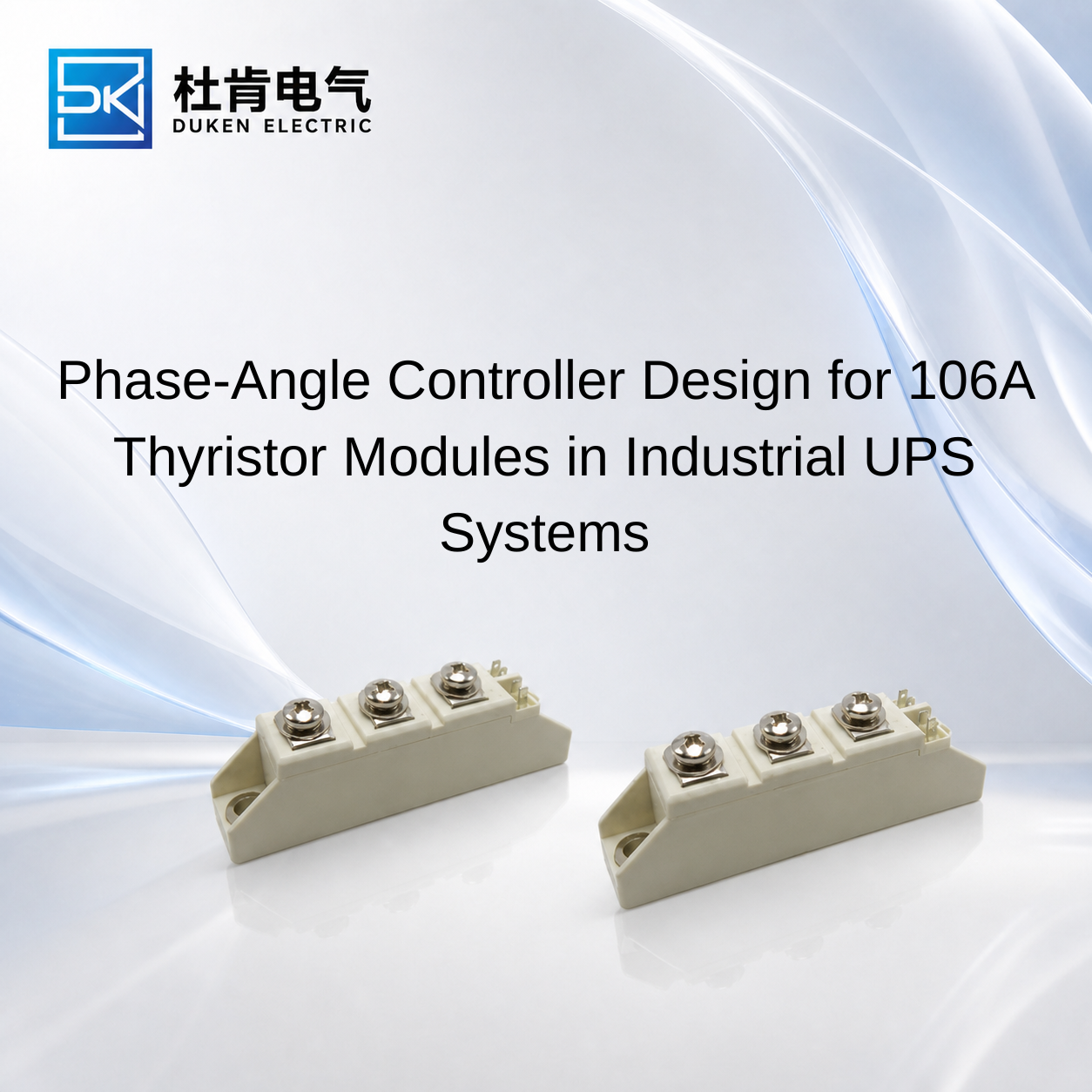
Phase-Angle Controller Design for 106A Thyristor Modules in Industrial UPS Systems
Choosing Compatible driver circuits and controllers for thyristor modules is especially important when a 106A SCR is used for phase-angle control in an industrial UPS. The controller must deliver more than a basic gate pulse: firing must be synchronized with the AC waveform, gate current must provide adequate triggering margin, and the circuit must remain stable during voltage transients, temperature changes, and abnormal load conditions. For UPS manufacturers and engineers replacing an existing module, controller compatibility should be checked together with forward voltage, surge capability, thermal resistance, package construction, and mounting requirements before a new SCR is approved.
How Phase-Angle Control Works with a 106A Thyristor Module
A conventional thyristor is a latching power semiconductor. When forward voltage is present and sufficient gate current is applied, the SCR turns on. After it has latched, removing the gate signal does not normally turn the device off. Conduction continues until main current falls below the holding-current level.
This behavior makes SCRs suitable for line-frequency phase control. The controller detects the AC waveform and delays the gate pulse by a selected firing angle. Earlier triggering allows conduction over a larger portion of the waveform, while later triggering reduces the conduction interval.
In a controlled rectifier, this technique can regulate average DC output. Similar principles can be applied in AC power-control sections where controlled conduction is required.
This explains why Compatible driver circuits and controllers for thyristor modules cannot be selected only according to nominal module current. The controller must be compatible with the actual gate characteristics and power-stage topology.
IGT, the gate trigger current, and VGT, the gate trigger voltage, are fundamental parameters. They specify triggering behavior under defined conditions, but a practical gate circuit normally needs sufficient operating margin to account for temperature, component tolerances, wiring impedance, and production variation.
The controller should also provide properly timed pulses. Poor synchronization can cause inconsistent conduction between cycles and disturb the expected output waveform. In multi-device rectifier circuits, firing sequence becomes even more important because each thyristor must conduct at the correct point in the supply cycle.
For replacement projects, engineers should therefore verify both the module datasheet and the controller output rather than assuming that two 106A SCR modules require identical gate-drive conditions.
Surge-Protection Low Forward-Voltage Phase-Angle-Control 106A Thyristor Module for UPS Systems
A surge-protection low forward-voltage phase-angle-control 106A thyristor module for ups systems is attractive because it combines three characteristics that can influence UPS reliability: controllable firing, conduction efficiency, and transient capability.
Forward or on-state voltage VT is particularly important during sustained conduction. A simplified conduction-loss estimate is:
Pcond ≈ VT × IT(avg)
At high current, this loss becomes significant. A lower VT under comparable operating conditions can help reduce semiconductor dissipation and therefore ease the thermal burden on the heat sink.
However, purchasing teams should compare VT under similar current and junction-temperature conditions. A lower number measured under different conditions does not automatically prove that one module will generate less heat in the real UPS.
Surge capability requires similar care.
ITSM describes the specified non-repetitive surge on-state current capability of an SCR. It represents short-duration abnormal stress rather than continuous current capability. I²t can additionally support coordination between the semiconductor and fast-acting protection.
For a surge-protection low forward-voltage phase-angle-control 106A thyristor module for ups systems, surge protection should be treated as a system function. Appropriate semiconductor fuses, transient suppression, transformer impedance, and fault-response strategy can all influence the stress experienced by the module.
The controller also plays a role. It should not produce inappropriate firing during abnormal supply conditions, and the overall design should ensure predictable triggering when voltage and load conditions are within the intended operating range.
dv/dt capability should be considered when the SCR is blocking. Rapid voltage transitions can produce displacement current through internal capacitance, increasing the risk of unintended triggering if the device and surrounding circuit are poorly coordinated.
Therefore, good phase-angle control combines accurate firing with suitable electrical protection rather than relying on the SCR's maximum ratings alone.
Thermal Cycling and Driver Reliability in A46-Version Modules
Long-life UPS equipment rarely operates at one fixed thermal condition. Load can vary during battery charging, normal operation, bypass conditions, and other operating modes. Cooling conditions may also change with ambient temperature and fan operation.
An A46-version full-module thermal-cycle-resistant 106A thyristor module for ups systems should consequently be evaluated as part of the complete thermal and electrical assembly.
Repeated heating and cooling can stress internal semiconductor interfaces because different materials expand and contract differently. For long-term industrial service, stable mechanical construction and controlled manufacturing can therefore be important.
The exact meaning of an A46 designation, however, should be confirmed from the relevant manufacturer's documentation. A version name alone does not establish a specific thermal-cycle test, lifetime, or electrical rating.
Controller behavior should also be checked over temperature.
Gate trigger characteristics are not necessarily identical across the complete operating-temperature range. A driver that provides only minimal triggering margin during room-temperature testing may become less reliable under different thermal conditions.
For an A46-version full-module thermal-cycle-resistant 106A thyristor module for ups systems, engineers should therefore qualify both thermal behavior and gate triggering under representative operating conditions.
Testing can include sustained operation at relevant load, repeated changes in operating state, and temperature monitoring of the module and cooling assembly. The objective is to verify that the driver continues to trigger the SCR reliably while the thermal system maintains adequate junction-temperature margin.
This is particularly important when qualifying a second-source module. Mechanical similarity does not prove that the replacement will behave identically across the UPS operating range.
Low Rth(j-c) Modules and Their Impact on Controller Selection
A screw-mount certified low Rth(j-c) 106A thyristor module for ups systems can be attractive when thermal performance is a priority.
Rth(j-c) describes the thermal resistance between the semiconductor junction and the case. For a given amount of device power loss, lower thermal resistance can reduce the temperature difference between these two points.
A simplified relationship is:
Tj = Tc + P × Rth(j-c)
This does not describe the complete junction-to-ambient thermal path. The thermal interface, heat sink, airflow, and ambient temperature still contribute to actual operating temperature.
The screw-mount structure must also be installed correctly. The module should have proper contact with the cooling surface, and the manufacturer's specified mounting procedure should be followed. Buyers should avoid applying generic torque assumptions to a module when its specific installation requirements have not been verified.
For a screw-mount certified low Rth(j-c) 106A thyristor module for ups systems, any certification claim should also be supported by appropriate documentation when certification forms part of the purchasing requirement.
How does this relate to the driver circuit?
Lower thermal resistance does not change the basic operating principle of the SCR, but thermal conditions can influence semiconductor characteristics. The gate driver should therefore provide appropriate trigger margin throughout the intended temperature range rather than being optimized only for one laboratory condition.
This illustrates why controller and thermal design should not be treated as completely separate engineering tasks.
SCR Controller Compatibility Compared with IGBT and MOSFET Drivers
An SCR controller, IGBT gate driver, and MOSFET gate driver perform fundamentally different functions.
The SCR controller supplies the triggering signal necessary to initiate conduction. In a phase-angle system, it must also synchronize firing with the AC waveform. Once the SCR has latched, the gate does not normally control turn-off.
IGBTs and MOSFETs require active switching control. Their drivers repeatedly charge and discharge the gate to command both turn-on and turn-off, often at much higher switching frequencies than an SCR phase-control system.
This distinction matters when an OEM considers modernizing an older UPS.
Changing from an SCR to an IGBT is not simply a matter of installing a different driver board. The converter topology, control strategy, protection, switching losses, filtering, and electromagnetic behavior may all change.
Rectifier diodes are different again because they require no gate controller. They are useful for uncontrolled rectification but cannot provide the firing-angle control of an SCR.
For existing line-frequency UPS functions, a properly matched SCR and phase-angle controller can therefore remain a practical solution. Engineers can improve thermal or surge performance by selecting a better-suited module without redesigning the entire power stage.
Conclusion
Selecting Compatible driver circuits and controllers for thyristor modules requires coordinated evaluation of the gate circuit and the power semiconductor.
For a 106A phase-controlled UPS application, the controller should provide appropriate IGT and VGT margin, accurate waveform synchronization, reliable firing over temperature, and stable operation in the expected electrical environment. The module should simultaneously provide suitable blocking voltage, VT, ITSM, I²t, dv/dt, di/dt, and thermal performance.
Low forward voltage can help reduce conduction loss, while low Rth(j-c) can improve the junction-to-case thermal path. Thermal-cycle-resistant construction may support demanding duty cycles, but manufacturer-specific claims and version designations should always be verified from technical documentation.
For OEM engineers and procurement managers, the safest replacement strategy is therefore to qualify the SCR, driver, protection network, and cooling system together. A module that looks superior on a datasheet still needs to operate correctly with the controller already responsible for firing it.
FAQ
Q1: What determines whether a phase-angle controller is compatible with a 106A SCR?
Important factors include IGT, VGT, gate configuration, firing-pulse timing, isolation, internal module topology, and operating-temperature range.
Q2: Does lower forward voltage improve UPS efficiency?
Lower VT can reduce SCR conduction loss under comparable operating conditions, although total UPS efficiency depends on the complete power system.
Q3: Why is ITSM important in a UPS thyristor module?
ITSM indicates specified non-repetitive surge-current capability and helps engineers evaluate the SCR against possible short-duration abnormal current events.
Q4: Does lower Rth(j-c) eliminate the need for a good heat sink?
No. Rth(j-c) covers only the junction-to-case thermal path. Interface resistance, heat-sink performance, airflow, and ambient temperature remain important.
Q5: Can a modern IGBT controller replace an SCR phase-angle controller?
Not directly. IGBTs use active turn-on and turn-off and generally require a different power-stage topology, control strategy, protection system, and gate driver.
READ MORE:
Procurement Guide to Low-Forward-Voltage 200A 400V Fast Recovery Diodes for Industrial Drives
Replacement Guide for Low-VF 200A 400V Fast Recovery Diodes in Industrial Inverters
Thermal Design Strategies for Low-VF 200A 400V Fast Recovery Diodes in Motor Drives
Low Qrr vs Low Forward Voltage: Selecting a 200A 400V Fast Recovery Diode for Frequency Inverters
Why Low Forward Voltage Matters in 200A 400V Fast Recovery Diodes
Controller Selection and Procurement Guide for 106A Thyristor Modules in UPS Systems
Selecting a Replacement 106A Thyristor Module Without Redesigning the UPS Controller
Thermal-Cycle Reliability and Driver Matching for 106A Thyristor Modules in UPS Systems
How to Match Driver Circuits with 106A Thyristor Modules in UPS Systems