
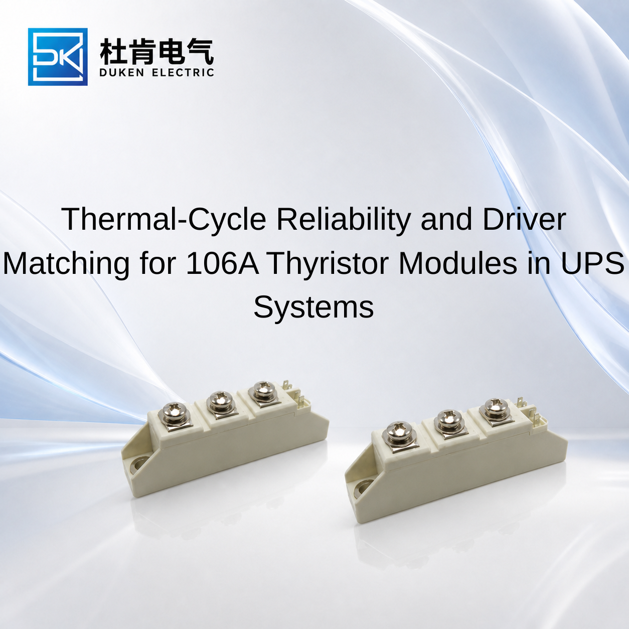
Thermal-Cycle Reliability and Driver Matching for 106A Thyristor Modules in UPS Systems
Long-term UPS reliability depends on more than selecting an SCR with sufficient current and voltage ratings. Compatible driver circuits and controllers for thyristor modules must continue to provide reliable triggering while the power module experiences changing load, temperature, and electrical stress. This becomes particularly important in 106A-class UPS designs exposed to repeated startup, charging, bypass, and load-transfer cycles. A technically suitable module must combine stable gate characteristics with acceptable conduction loss, thermal resistance, surge capability, and mechanical construction. For OEM engineers and procurement teams, thermal-cycle performance and driver compatibility should therefore be evaluated together rather than as separate specifications.
Why Thermal Cycling Matters in A46-Version 106A Thyristor Modules
An A46-version full-module thermal-cycle-resistant 106A thyristor module for ups systems may be considered when equipment is expected to experience repeated changes in semiconductor temperature.
Temperature cycling occurs whenever the module moves between different power levels. During high-current conduction, on-state losses heat the semiconductor. When current decreases or the UPS enters another operating state, the module begins to cool. This repeated heating and cooling creates expansion and contraction within the assembly.
Different materials inside a power semiconductor package do not necessarily expand at identical rates. Over long service periods, repeated thermal stress can therefore affect interfaces, connections, insulation structures, and mechanical integrity.
This is one reason industrial buyers should not judge reliability only from maximum junction temperature. The fact that a module can tolerate a specified maximum Tj does not mean operating repeatedly near that limit is desirable.
Thermal margin remains important.
The exact meaning of “A46-version” should also be verified with the specific manufacturer. A version designation does not, by itself, define a universal thermal-cycle requirement. Buyers should obtain the corresponding technical documentation before using the designation as a qualification criterion.
For an A46-version full-module thermal-cycle-resistant 106A thyristor module for ups systems, practical qualification should reproduce the expected UPS duty cycle as closely as possible. Rather than performing only a short full-load test, engineers should evaluate how temperature changes during realistic transitions between operating conditions.
The gate controller should be monitored during these tests as well. If triggering becomes inconsistent at different temperatures, the thermal robustness of the package alone cannot guarantee reliable system operation.
How Gate Trigger Margin Changes the Reliability Picture
Understanding Compatible driver circuits and controllers for thyristor modules requires a clear distinction between a threshold value and a reliable operating condition.
IGT represents gate trigger current under specified test conditions, while VGT describes the associated gate trigger voltage characteristics. These parameters help engineers determine whether a controller can initiate SCR conduction.
A common design risk is treating the published trigger requirement as the exact output the controller should provide.
Industrial gate circuits normally require appropriate margin because the actual trigger path includes the controller output, isolation components, wiring, connectors, gate resistance, and the thyristor itself. Temperature and production variation can also influence triggering behavior.
For an existing UPS, this becomes particularly relevant when changing thyristor suppliers. Two devices may both be described as 106A modules while having different gate characteristics.
The controller should therefore be checked against the candidate module rather than assumed to be universally compatible with the current class.
Pulse timing also matters.
In phase-angle control, the firing pulse must correspond to the intended point in the AC waveform. If the controller produces inconsistent timing, the conduction waveform can change. In multi-thyristor circuits, poor firing coordination can create uneven electrical loading between devices.
A surge-protection low forward-voltage phase-angle-control 106A thyristor module for ups systems therefore requires a controller capable of both adequate gate drive and accurate synchronization.
The gate signal should also remain stable in an electrically noisy environment. Appropriate isolation and circuit layout can help prevent disturbances on the power side from interfering with low-level control electronics.
Conduction Loss, Surge Stress and Controller Coordination
A surge-protection low forward-voltage phase-angle-control 106A thyristor module for ups systems must handle two very different forms of electrical stress: normal conduction and short-duration abnormal current.
During normal operation, on-state voltage contributes to semiconductor power loss. A useful first-order estimate is:
Pcond ≈ VT × IT(avg)
For UPS equipment operating for long periods, this loss directly affects the module's thermal cycle. Higher dissipation means a greater temperature rise for the same cooling conditions.
When comparing modules, VT should be evaluated at relevant current and temperature conditions rather than comparing isolated headline numbers from different datasheets.
Short-duration surge stress is different.
ITSM represents specified non-repetitive surge on-state current capability. It describes the ability of the SCR to tolerate a defined transient current event, not the current it should repeatedly conduct.
I²t provides another useful parameter when coordinating semiconductor protection. A properly designed protection system should limit fault energy so that the SCR is not exposed beyond its specified capability.
The phase-angle controller also needs predictable behavior during disturbances. Although the driver itself cannot replace power-stage protection, inappropriate firing during abnormal supply conditions can complicate fault behavior.
dv/dt is another concern when the SCR is blocking. Rapid voltage changes can produce displacement current:
i = C × dv/dt
Adequate thyristor dv/dt capability, gate-circuit design, snubber arrangements where necessary, and appropriate transient suppression should therefore work together.
For procurement teams, “surge-protection” should not be interpreted as a feature residing entirely inside the module. Semiconductor ratings and external protection architecture must be coordinated.
Low Rth(j-c), Screw Mounting and Thermal Design
A screw-mount certified low Rth(j-c) 106A thyristor module for ups systems offers another path toward improved thermal performance.
Rth(j-c) represents thermal resistance from the semiconductor junction to the module case. Lower Rth(j-c) means that, for the same device power dissipation, the junction-to-case temperature rise can be lower.
The basic relationship can be expressed as:
Tj = Tc + P × Rth(j-c)
This equation is useful for understanding the role of module thermal resistance, but it does not describe the entire thermal system.
Heat must continue from the module case through the thermal interface into the heat sink and then into the surrounding environment. Poor mounting contact or inadequate heat-sink performance can therefore cancel much of the advantage provided by low internal thermal resistance.
For a screw-mount certified low Rth(j-c) 106A thyristor module for ups systems, mechanical installation deserves particular attention. The mounting surface should be appropriate for the module, and the manufacturer's installation instructions should be followed.
Generic torque assumptions should not be applied without checking the relevant product documentation.
If “certified” is part of the purchasing requirement, the buyer should also establish which certification is being referenced and request the corresponding documentation.
Thermal qualification should ideally monitor case temperature during representative operation. Engineers can then estimate whether adequate junction-temperature margin remains under the expected load and cooling conditions.
This becomes especially valuable when comparing an original SCR with a replacement from another supplier.
SCR Drivers Compared with IGBT, MOSFET and Diode Solutions
The relationship between the semiconductor and its controller becomes clearer when SCR technology is compared with other power devices.
A rectifier diode requires no gate signal. It conducts according to circuit polarity and is appropriate for uncontrolled rectification. It cannot directly replace an SCR where controlled firing is required.
An SCR adds controlled turn-on. Once triggered and latched, however, a conventional SCR cannot normally be turned off through its gate. Current must fall below the holding-current level.
This makes phase-angle controllers particularly suitable for line-frequency SCR applications.
IGBTs operate differently. Their gates provide active turn-on and turn-off, allowing high-frequency PWM. This capability makes IGBTs important in UPS inverter stages but requires a different driver architecture.
MOSFETs also support active high-frequency switching and are commonly used where their voltage, current, and switching characteristics suit the converter design.
Moving from an SCR to an IGBT or MOSFET therefore requires more than changing the semiconductor and gate board. Switching strategy, protection, losses, control logic, filtering, and electromagnetic behavior may all change.
For existing line-frequency UPS functions, retaining SCR technology and qualifying the driver-module combination can therefore be considerably more practical than redesigning the complete power stage.
Conclusion
Thermal-cycle reliability and gate-driver compatibility are closely connected in industrial UPS applications. Compatible driver circuits and controllers for thyristor modules must provide stable triggering not only during initial room-temperature testing but across realistic electrical and thermal operating conditions.
For a 106A module, engineers should evaluate IGT, VGT, firing timing, VT, Rth(j-c), ITSM, I²t, dv/dt, thermal cycling, mechanical mounting, and cooling together.
An A46-version module may be relevant where thermal-cycle resistance is required, but manufacturer-specific documentation should define what the designation actually represents. Low Rth(j-c) can improve the internal thermal path, while low VT can reduce conduction loss, but neither parameter removes the need for adequate system cooling.
For UPS manufacturers qualifying alternative components, testing the SCR and controller together under representative duty cycles provides stronger evidence of compatibility than comparing model numbers alone. This system-level approach helps procurement teams distinguish a genuinely suitable replacement from a module that merely appears similar on paper.
FAQ
Q1: Why does thermal cycling matter for UPS thyristor modules?
Repeated heating and cooling can create mechanical stress within the module as different materials expand and contract during changing load conditions.
Q2: What should be checked when matching a gate controller to a 106A SCR?
Engineers should verify IGT, VGT, gate configuration, firing timing, isolation, temperature behavior, and the controller's available trigger margin.
Q3: Does low Rth(j-c) guarantee lower junction temperature?
Not by itself. Actual junction temperature also depends on semiconductor losses, thermal-interface quality, heat-sink performance, airflow, and ambient temperature.
Q4: What is the difference between ITSM and normal current rating?
ITSM describes specified non-repetitive surge-current capability, while the normal current rating applies under defined repetitive operating and thermal conditions.
Q5: Can an IGBT driver replace an SCR phase-angle controller?
No direct substitution should be assumed. IGBTs require active turn-on and turn-off control and typically operate within a different converter architecture.
READ MORE:
Procurement Guide to Low-Forward-Voltage 200A 400V Fast Recovery Diodes for Industrial Drives
Replacement Guide for Low-VF 200A 400V Fast Recovery Diodes in Industrial Inverters
Thermal Design Strategies for Low-VF 200A 400V Fast Recovery Diodes in Motor Drives
Low Qrr vs Low Forward Voltage: Selecting a 200A 400V Fast Recovery Diode for Frequency Inverters
Why Low Forward Voltage Matters in 200A 400V Fast Recovery Diodes
Controller Selection and Procurement Guide for 106A Thyristor Modules in UPS Systems
Selecting a Replacement 106A Thyristor Module Without Redesigning the UPS Controller
Phase-Angle Controller Design for 106A Thyristor Modules in Industrial UPS Systems
How to Match Driver Circuits with 106A Thyristor Modules in UPS Systems