
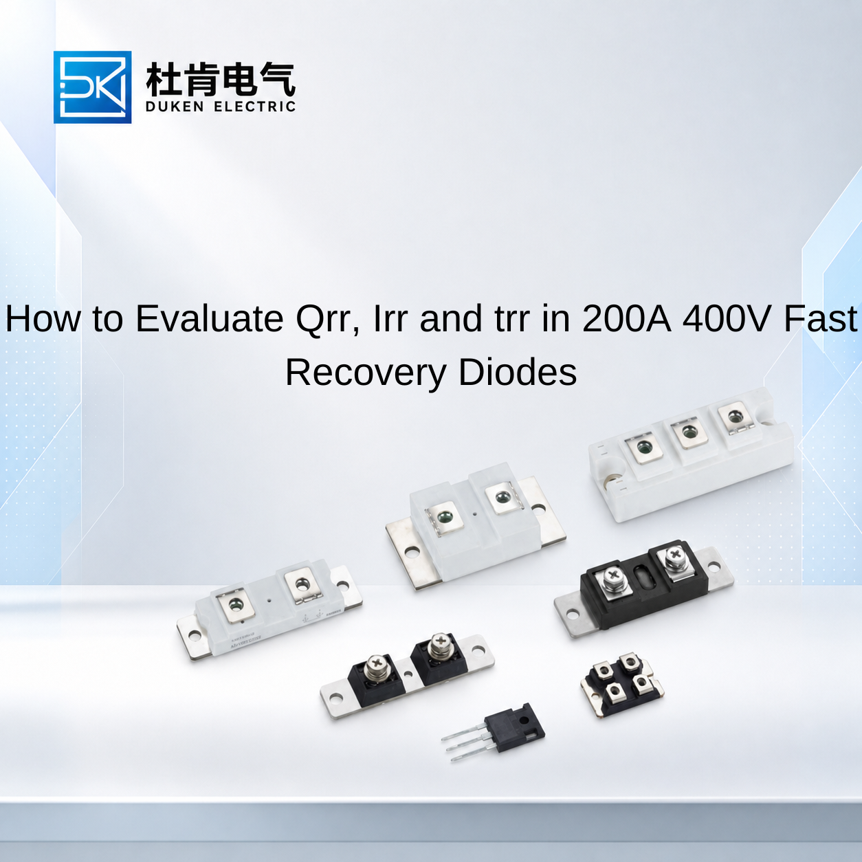
How to Evaluate Qrr, Irr and trr in 200A 400V Fast Recovery Diodes
Understanding Qrr in 200A 400V Fast Recovery Diodes: What Buyers Must Know requires more than finding the reverse recovery charge value in a datasheet. For industrial equipment manufacturers and component distributors, Qrr should be evaluated together with peak reverse recovery current (Irr), reverse recovery time (trr), forward voltage, leakage current, temperature, and the conditions used for measurement. These parameters become particularly important when qualifying a replacement diode for welding equipment, UPS systems, motor drives, industrial rectifiers, or high-frequency power converters. Two 200A 400V devices can share the same headline ratings while producing noticeably different switching behavior once installed in the same circuit.
Understanding the Relationship Between Qrr, Irr and trr
When a silicon fast recovery diode conducts forward current, charge carriers are stored in the semiconductor. If the circuit suddenly applies reverse voltage, the diode cannot establish its reverse blocking state instantaneously. Stored charge must first be removed, producing a temporary reverse current.
Three parameters are commonly used to describe this process.
Reverse recovery time, trr, represents the duration of the recovery interval under specified measurement conditions. Peak reverse recovery current, Irr, describes the maximum reverse current reached during that transition. Qrr represents the charge associated with the reverse recovery waveform and can be expressed conceptually as:
Qrr = ∫ |iR(t)| dt
These parameters are related, but they are not interchangeable.
For example, two diodes may show similar trr values while having different recovery-current amplitudes and therefore different Qrr. Conversely, focusing only on Qrr can hide differences in the shape of the recovery waveform.
Recovery behavior is also influenced by forward current before commutation, junction temperature, current rate of change and circuit conditions. This means a buyer should not compare a Qrr value measured under one set of conditions directly with another value measured under substantially different conditions.
This is a fundamental part of Understanding Qrr in 200A 400V Fast Recovery Diodes: What Buyers Must Know. When reviewing competing datasheets, procurement engineers should examine the test-condition notes beside Qrr, Irr and trr instead of copying only the numerical values into a comparison sheet.
If one supplier does not publish sufficiently detailed dynamic data, representative sample testing can provide a more reliable comparison.
Evaluating Vishay Equivalent Diodes for Replacement Projects
Replacement sourcing often begins when an established component has a long lead time, rising cost, or limited availability. A buyer may therefore search for a brand Vishay equivalent glass-metal seal housing low conduction loss 200A 400V fast recovery diode.
The word “equivalent,” however, should be treated carefully.
Matching the 200A current class and 400V blocking voltage is only the first step. The replacement should also be compared for forward voltage, Qrr, trr, reverse leakage, thermal resistance, surge-current capability, junction-temperature limits, package dimensions, and polarity.
Forward voltage deserves particular attention because it contributes directly to conduction loss. A useful first-order approximation is:
Pcond ≈ VF × IF(avg)
At high current, a small difference in VF can produce a meaningful change in heat generation.
A brand Vishay equivalent glass-metal seal housing low conduction loss 200A 400V fast recovery diode should therefore balance conduction and recovery performance. Selecting a very low-VF device without checking Qrr may increase switching-related losses in a faster converter. Selecting solely for extremely low Qrr while accepting significantly higher forward loss may be equally undesirable in an application with long conduction intervals.
The original diode should serve as the engineering reference rather than simply as a model number.
For an OEM replacement project, engineers can test the original and candidate under the same DC bus voltage, load-current range, switching conditions, cooling arrangement, and ambient temperature. Case and heat-sink temperatures can then be compared after the system approaches thermal equilibrium.
This approach provides stronger evidence of compatibility than assuming that similar datasheet headings mean identical behavior.
Selecting a 3/4″-16UNF Stud Type for Bridge Rectifier Applications
Dynamic characteristics are only one part of diode qualification. Mechanical compatibility can become equally important when replacing a stud-mounted device.
A 3/4″-16UNF stud type for bridge rectifier module stud mount DO-9 200A 400V fast recovery diode may be required because an existing rectifier assembly has already been designed around that package format.
In this situation, engineers should verify the thread and overall dimensions, but they should not stop there.
Stud polarity is critical. Depending on the diode configuration, the stud may be electrically connected to the anode or cathode. If a conductive heat sink forms part of the electrical path, installing the opposite-polarity version can make the replacement incompatible even though the external dimensions are similar.
Thermal design must also be considered. A stud-mounted package transfers heat through its mechanical interface into the mounting structure. The manufacturer's installation requirements should therefore be followed to maintain reliable thermal contact.
For a 3/4″-16UNF stud type for bridge rectifier module stud mount DO-9 200A 400V fast recovery diode, the importance of Qrr depends strongly on the circuit topology.
In a conventional 50/60 Hz rectifier, the diode changes conduction state relatively infrequently compared with an inverter operating at several kilohertz. In such an application, forward voltage, surge-current capability, thermal resistance, current sharing, and cooling may dominate the selection process.
In a switched rectifier or commutation circuit, Qrr, Irr and trr deserve much greater attention.
This application-dependent approach prevents buyers from paying for dynamic performance that provides little system benefit while also preventing the opposite mistake: installing a slow-recovery device into equipment that depends on fast commutation.
Why Recovery Waveform Matters in High-Speed Industrial Converters
For a high switching speed industrial power converter low reverse leakage current 200A 400V fast recovery diode, the recovery waveform can influence both diode performance and the stress imposed on the associated transistor.
Consider an IGBT commutating current from a freewheeling diode. When the IGBT turns on, the diode may still conduct reverse recovery current for a short period. The transistor therefore carries additional current during its turn-on transition.
This contributes to switching energy and can increase junction temperature.
The interaction becomes more important as switching frequency increases because the event occurs repeatedly:
Psw ≈ Esw × fs
Circuit parasitic inductance can also convert rapid current transitions into voltage stress:
V = L × di/dt
Therefore, a large or abrupt recovery-current waveform can contribute to voltage overshoot and ringing. Busbar design, semiconductor lead length, snubber configuration, gate resistance, and IGBT switching speed all influence the final result.
This is why a high switching speed industrial power converter low reverse leakage current 200A 400V fast recovery diode should not be selected solely from a trr specification.
A diode with a short recovery time but a large recovery-current peak may interact differently with the converter from a device whose recovery is more gradual. The actual waveform should be considered when detailed manufacturer data are available.
Reverse leakage provides additional information about blocking behavior, but it must also be interpreted under stated temperature and voltage conditions. Leakage current generally increases with junction temperature. Comparing one supplier's room-temperature leakage value against another supplier's elevated-temperature specification is therefore misleading.
For demanding OEM applications, double-pulse or representative converter testing can help engineers observe the practical relationship between diode recovery and transistor switching behavior.
Choosing Between Standard Rectifier, Silicon FRD and SiC Diodes
Understanding Qrr in 200A 400V Fast Recovery Diodes: What Buyers Must Know also helps buyers determine whether a fast recovery diode is actually the correct technology.
Standard silicon rectifier diodes remain suitable for many line-frequency applications. Their advantages can include mature manufacturing, robust high-current packages, good surge capability, and competitive cost. Where commutation is slow, extremely low Qrr provides limited practical value.
Silicon fast recovery diodes are designed for applications requiring faster transition from forward conduction to reverse blocking. They are widely used in industrial converters because they combine established silicon technology with significantly improved recovery performance compared with standard rectifiers.
SiC Schottky diodes take a different approach. Their very low minority-carrier reverse recovery can significantly reduce recovery-related switching stress in high-frequency systems.
This can be valuable in modern converters seeking higher switching frequency, lower switching loss, or increased power density.
However, SiC is not automatically a direct upgrade for every 200A 400V silicon FRD. Buyers must still consider forward conduction behavior, surge requirements, package format, mechanical integration, cooling, availability, and total system cost.
For existing industrial equipment built around a DO-9 stud package, a qualified silicon FRD may provide a simpler replacement path. In a new high-frequency converter, SiC may provide greater system-level benefits if the surrounding circuit is designed to take advantage of its switching characteristics.
The correct choice therefore comes from matching semiconductor technology to the application rather than ranking technologies by Qrr alone.
Conclusion
Evaluating Qrr correctly means understanding how reverse recovery charge relates to Irr, trr, forward voltage, leakage current, temperature, and the actual commutation circuit.
For lower-frequency bridge rectifiers, conduction loss, thermal performance, surge capability, and mechanical compatibility may dominate the purchasing decision. For high-frequency converters, reverse recovery characteristics become much more influential because they affect switching losses, transistor stress, voltage overshoot, and thermal performance.
Industrial buyers should therefore compare 200A 400V fast recovery diodes using complete electrical and mechanical data, paying close attention to the conditions under which dynamic parameters are specified.
When the component is intended as a replacement or second source, representative sample testing under realistic equipment conditions provides the strongest evidence of compatibility. This practical approach turns Qrr from a datasheet number into a useful engineering tool for improving sourcing decisions and reducing the risk of field failures.
FAQ
Q1: What is the difference between Qrr and trr?
Qrr represents the charge involved during reverse recovery, while trr represents the duration of the recovery process under specified test conditions.
Q2: Does a shorter trr always mean lower switching loss?
No. The magnitude and shape of the reverse recovery current also matter, so Qrr and Irr should be considered together with trr.
Q3: What parameters should be checked when replacing a Vishay fast recovery diode?
Buyers should compare voltage and current ratings, VF, Qrr, trr, leakage, surge capability, thermal resistance, junction-temperature limits, package dimensions, and polarity.
Q4: Why is stud polarity important for DO-9 diodes?
The stud may be connected to either the anode or cathode depending on the device. Incorrect polarity can make an otherwise mechanically compatible diode unsuitable for an existing assembly.
Q5: Is SiC always preferable to a silicon fast recovery diode?
No. SiC offers major recovery advantages in high-frequency applications, but cost, conduction behavior, surge requirements, package compatibility, and overall system design must also be considered.
READ MORE:
From Emergency Stock to Long-Term Supply: Qualifying a 300A Phase Control Thyristor
Lead Time vs Technical Fit: Buying a 300A Phase Control Thyristor from Stock
Selecting an In-Stock 300A Phase Control Thyristor for High-Current Rectifier Systems
How In-Stock 300A Phase Control Thyristors Reduce Downtime in Industrial Power Systems
300A Phase Control Thyristor in Stock: What Industrial Buyers Should Verify Before Ordering
Supplier Qualification Checklist for 200A 400V Fast Recovery Diodes: From Qrr to Batch Consistency
Thermal and Reliability Risks of Qrr in 200A 400V Fast Recovery Diodes
How Qrr Influences Efficiency and Device Selection in 200A 400V Fast Recovery Diodes
Why Qrr Test Conditions Matter When Sourcing 200A 400V Fast Recovery Diodes