
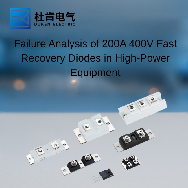
Failure Analysis of 200A 400V Fast Recovery Diodes in High-Power Equipment
Author: Selina
A 200A 400V fast recovery diode can fail through several mechanisms that are not obvious from a basic continuity test. In solar inverters, welding machines, motor drives, and bridge rectifier modules, the root cause may involve reverse recovery stress, voltage overshoot, thermal fatigue, mounting error, or inconsistent device quality. For OEMs and procurement teams, accurate failure analysis is essential because replacing a damaged diode without correcting the cause often leads to repeat failures.
Electrical Failure Modes That Buyers Should Understand
Reverse Recovery Overstress
When a fast recovery diode changes from forward conduction to reverse blocking, stored charge must be removed from the junction. This produces reverse recovery current. If the current peak, recovery charge, or di/dt exceeds the device capability, localized heating and electric-field stress can damage the die.
A fast reverse recovery for bridge rectifier module for motor drive application 200A 400V fast recovery diode should therefore be evaluated with the actual IGBT or MOSFET switching stage. Short reverse recovery time alone does not guarantee lower stress. Recovery softness, peak reverse current, busbar inductance, and junction temperature are equally important.
Oscilloscope measurements should be taken directly at the diode terminals with a low-inductance probe arrangement. Excessive ringing or overshoot may indicate poor layout, inadequate snubbing, or an unsuitable recovery profile.
Reverse Voltage Avalanche and Transients
A 400V diode can be overstressed even in a nominally lower-voltage system. Transformer leakage inductance, motor commutation, cable inductance, and abrupt switching can create spikes above VRRM. Repeated exposure may gradually degrade the junction before a final short-circuit failure occurs.
Engineers should compare measured peak reverse voltage with the repetitive and non-repetitive ratings. RC snubbers, TVS devices, improved busbar geometry, and slower switching transitions may be necessary.
Forward Current and Surge Damage
Welding machines and capacitor-charging circuits often generate high pulse current. If IFSM is exceeded, bond wires, die metallization, or the semiconductor junction can fail. The waveform duration and repetition rate matter as much as the peak amplitude.
Thermal Failure and Cooling Problems
Thermal stress is a leading cause of power diode failure. Forward loss, reverse recovery loss, poor heat transfer, elevated ambient temperature, and repeated thermal cycling can push the junction beyond its safe operating range.
Key checks include:
Forward voltage at actual current
Junction-to-case thermal resistance
Case-to-heat-sink interface quality
Heat-sink flatness and cleanliness
Cooling airflow or coolant flow
Maximum ambient temperature
Thermal cycling frequency
Infrared imaging can identify uneven heating, but the measurement must account for emissivity and package surface differences. Thermocouples near the baseplate provide useful comparative data.
DO-9 Stud-Mount Risks
A for solar inverter stud mount DO-9 used in welding machine 200A 400V fast recovery diode depends heavily on correct mounting torque. Excessive torque can crack internal structures, while insufficient torque increases thermal resistance.
The heat-sink surface should be flat, free of burrs, and coated with the correct amount of thermal compound. The top terminal must not be subjected to lateral force from a misaligned busbar. Polarity should also be checked carefully because stud-mount devices may be supplied in anode-stud or cathode-stud versions.
SOT-227 High-Temperature Risks
A SOT-227 package automotive application high temperature 150°C 200A 400V fast recovery diode requires careful review of what the 150°C rating means. It may represent maximum junction temperature rather than a recommended continuous operating point.
At high temperature, reverse leakage increases and recovery behavior can change. Baseplate flatness, screw torque, isolation quality, and molding integrity should be inspected. Where automotive qualification is claimed, buyers should request exact model-specific evidence rather than relying on package type alone.
How to Diagnose a Failed Diode
Begin with visual inspection. Look for discoloration, cracked molding, melted terminals, damaged threads, loose hardware, and signs of arcing. Next, compare forward voltage and reverse leakage with a known-good sample.
A simple multimeter can identify a shorted or open diode, but it cannot reveal recovery degradation, leakage at high voltage, or thermal instability. More complete analysis may include:
Curve tracing
High-voltage reverse leakage testing
Reverse recovery measurement
X-ray inspection
Decapsulation
Scanning acoustic microscopy
Cross-section analysis
The failure signature should be correlated with operating logs, cabinet temperature, fan condition, coolant flow, switching waveform, and recent maintenance history.
Compare the Device With Alternative Technologies
Standard rectifier diodes are robust for line-frequency use but usually unsuitable for fast switching. Schottky diodes offer low forward voltage and minimal recovery at lower voltage ranges, but leakage may be high. SiC diodes provide extremely low recovery charge and high-temperature performance, though they cost more and can change EMI behavior.
Integrated IGBT modules simplify assembly because the freewheeling diode is matched to the switch. However, failure of one internal element often requires replacement of the entire module. Separate fast recovery diodes offer more flexibility and easier component-level service.
Prevention and Procurement Controls
Failure prevention begins before purchase. Suppliers should provide controlled datasheets, maximum and typical recovery values, forward-voltage curves, surge-current data, thermal resistance, RoHS and REACH declarations, and lot traceability.
Before volume approval, test multiple samples under realistic electrical and thermal conditions. Recommended validation includes high-current forward testing, reverse leakage at elevated temperature, surge testing, recovery characterization, thermal cycling, and mounting-torque verification.
Purchase agreements should define approved factories, labeling requirements, date-code format, change notification, and failure-analysis response. These controls reduce the risk of silent die substitution or process changes.
Conclusion
Reliable failure analysis of a 200A 400V fast recovery diode requires more than confirming whether the device is open or shorted. Engineers should examine reverse recovery stress, voltage overshoot, surge current, thermal path, mounting quality, package condition, and supplier consistency.
For DO-9 devices, torque, heat-sink contact, and busbar stress are major factors. For SOT-227 devices, isolation, baseplate mounting, and high-temperature leakage deserve close attention. A structured investigation helps prevent repeat failures and improves long-term equipment availability.
Frequently Asked Questions
Why does a diode repeatedly fail after replacement?
The original root cause may remain, such as overshoot, cooling failure, incorrect torque, or excessive surge current.
Can a multimeter confirm diode health?
Only partially. It cannot evaluate recovery behavior, high-voltage leakage, or thermal stability.
What indicates reverse recovery stress?
High current spikes, ringing, voltage overshoot, and excessive switch turn-on loss are common indicators.
Can high temperature permanently damage the diode?
Yes. Repeated operation near or above the junction limit accelerates degradation.
Should failed parts be returned for laboratory analysis?
Yes, especially when failures repeat or involve safety-critical equipment.
SEO Keywords: 200A 400V fast recovery diode, fast recovery diode failure analysis, reverse recovery failure, diode voltage overshoot, diode thermal failure, DO-9 diode failure, SOT-227 diode failure, solar inverter diode, welding machine diode, motor drive diode, bridge rectifier diode, fast reverse recovery diode, surge current damage, high temperature diode, 150°C power diode, diode mounting torque, diode heat sink, reverse leakage current, reverse recovery charge, peak recovery current, recovery softness, forward voltage drop, semiconductor thermal cycling, power diode diagnostics, industrial rectifier failure, IGBT freewheeling diode, MOSFET switching diode, SiC diode comparison, Schottky diode comparison, standard rectifier diode, diode curve tracing, semiconductor X-ray inspection, diode supplier qualification, semiconductor traceability, RoHS compliant diode, REACH compliant diode, power electronics reliability, inverter failure analysis, welding rectifier repair, motor drive maintenance.
READ MORE:
Application Matching Guide for 200A 400V Fast Recovery Diodes
Incoming Inspection and Qualification Testing for 200A 400V Fast Recovery Diodes
Reliability Engineering for 200A 400V Fast Recovery Diodes in Solar Inverters and Welding Systems
Optimizing Fast Recovery Diodes for Motor Drive and Bridge Rectifier Performance
DO-9 vs SOT-227: Choosing the Right 200A 400V Fast Recovery Diode Package
Total Cost of Ownership for 106A Thyristor Modules in Industrial UPS Heating Projects
Common Failure Analysis of 106A Thyristor Modules in UPS-Supported Industrial Heating Equipment