
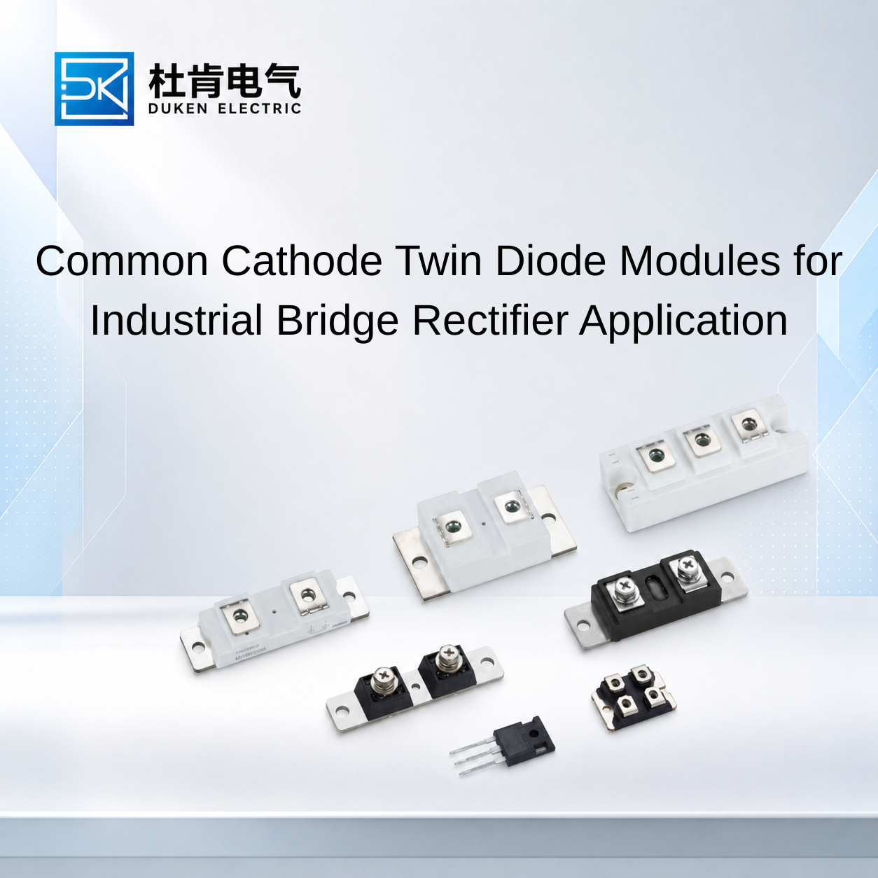
Common Cathode Twin Diode Modules for Industrial Bridge Rectifier Applications
Author: Selina
A 200A 400V fast recovery diode in a common-cathode twin-diode configuration can provide a practical solution for industrial bridge rectifiers, motor drive converters, and inverter power supplies. By integrating two diode elements into one semiconductor package with a shared cathode connection, this design helps simplify power-stage construction and reduce the number of individual components required. However, selecting a suitable module requires a clear understanding of its internal circuit, current paths, voltage distribution, reverse recovery behavior, and thermal characteristics. For industrial OEM engineers, correct module configuration is essential for reliable rectification and efficient power conversion.
1. Understanding Common Cathode Twin Diode Module Construction
A twin diode module integrates two semiconductor diode elements within one package.
In a common-cathode configuration, both diode elements share a single cathode terminal, while their anodes remain electrically independent.
Internal Electrical Structure
The simplified circuit can be represented as:
       Anode 1          Anode 2
          |                |
         D1               D2
          |                |
          +-------+--------+
                  |
             Common Cathode
The actual internal construction and terminal numbering must always be verified using the manufacturer's circuit diagram.
How the Two Diodes Operate
Each diode branch operates independently according to its applied voltage and current path.
When the anode voltage becomes sufficiently positive relative to the shared cathode, the corresponding diode conducts.
When the polarity reverses, the diode blocks current after completing its reverse recovery process.
This arrangement allows the two diode elements to support separate branches within a common electrical topology.
Common Cathode Versus Common Anode
Characteristic | Common Cathode | Common Anode |
|---|---|---|
Shared terminal | Cathode | Anode |
Independent terminals | Two anodes | Two cathodes |
Electrical polarity | Shared negative-side connection | Shared positive-side connection |
Application | Depends on circuit topology | Depends on circuit topology |
Direct interchangeability | No | No |
The distinction is important when selecting replacement modules.
A module with the wrong internal connection may not fit the existing circuit even if its package dimensions and current rating are identical.
2. Applying Twin Diode Modules in Bridge Rectifier Circuits
Bridge rectifiers convert alternating current into direct current by directing current through the load in a consistent direction.
A conventional single-phase full bridge uses four diode elements.
Industrial applications may use individual diodes, dual-diode modules, or integrated bridge rectifier modules depending on the required power level and mechanical design.
Role of Twin Diode Modules
A common-cathode twin-diode module can be used as part of a rectifier assembly where two diode branches require a shared cathode connection.
Two such modules may be incorporated into suitable bridge arrangements, depending on the selected circuit topology.
The exact connections must be determined from the internal circuit diagrams rather than assumed from the module name.
Current Flow During Positive and Negative AC Half-Cycles
During the positive half-cycle, one pair of rectifying elements conducts and establishes the required load-current direction.
During the negative half-cycle, another pair conducts, maintaining the same current direction through the load.
This full-wave rectification process produces a pulsating DC output.
The output waveform can be smoothed using suitable DC-side filtering.
Industrial Bridge Rectifier Applications
Common applications include:
Industrial DC power supplies.
Motor drive input stages.
Battery charging equipment.
Welding inverter front ends.
Industrial automation equipment.
DC excitation systems.
For a common cathode for bridge rectifier module twin diode 200A 400V fast recovery diode application, engineers should verify the module's internal connections, repetitive reverse voltage, current ratings, and cooling conditions.
Six-Pulse and Other Rectifier Architectures
Three-phase industrial rectifiers can use multiple diode elements to form six-pulse bridge configurations.
These arrangements provide higher power capability than many single-phase solutions and are widely used in industrial equipment.
However, the number and configuration of diode modules depend on the selected rectifier architecture.
A twin-diode module should only be used where its electrical topology matches the required current paths.
3. Electrical Parameters for Selecting a 200A 400V Twin Diode
A module's nominal current and voltage ratings are only the starting point for component selection.
Engineers should review the full datasheet.
Current Ratings
Parameter | Symbol | Importance |
|---|---|---|
Average forward current | IF(AV) | Continuous current capability |
RMS forward current | IF(RMS) | Thermal loading |
Non-repetitive surge current | IFSM | Fault-current withstand |
Forward voltage | VF | Conduction losses |
Junction temperature | Tj(max) | Thermal operating limit |
A particularly important consideration is whether the 200A rating applies to each diode element or to the complete module under specified conditions.
This must be confirmed with the manufacturer.
If both diode branches operate simultaneously, combined package heating must be considered.
Reverse Voltage Rating
VRRM defines the repetitive peak reverse-voltage rating.
The selected device must withstand the maximum reverse voltage imposed across each diode during normal operation and foreseeable transients.
A 400V rating should not be interpreted as compatibility with every 400V AC power system.
Engineers must calculate peak voltage and account for switching overshoot and circuit conditions.
Forward Voltage Drop
Forward voltage influences conduction losses.
A simplified relationship is:
Actual losses depend on current waveform and temperature.
For a twin-diode module, the thermal design should account for the losses of both diode elements.
Reverse Recovery Characteristics
Fast recovery behavior is important in switching converters.
The main specifications include:
Reverse recovery time, trr.
Reverse recovery charge, Qrr.
Peak reverse recovery current, IRRM.
These characteristics influence switching losses and the stress imposed on IGBTs or MOSFETs.
A diode intended for line-frequency rectification may not be suitable for a high-frequency inverter stage.
4. Thermal Management and Mechanical Integration
Twin-diode modules provide a compact package, but their thermal performance must be carefully evaluated.
Combined Thermal Loading
When both diode elements operate, heat generated by each branch can influence the temperature of the shared package.
Therefore, engineers should not assume that each element can independently dissipate its maximum rated power at the same time.
The manufacturer’s thermal model and derating information should be reviewed.
Thermal Resistance
For a suitable cooling arrangement, a simplified junction-temperature model is:
Where the total thermal resistance includes the junction-to-case, interface, and heat-sink-to-ambient paths.
For dual-diode modules, mutual thermal coupling may need to be considered.
Heat-Sink Selection
The heat sink should be selected according to:
Total diode losses.
Maximum ambient temperature.
Required junction-temperature margin.
Airflow.
Installation space.
Cooling method.
Forced-air cooling may be appropriate for high-current rectifier assemblies.
For more demanding power-density requirements, liquid cooling may be considered.
Mechanical Compatibility
Before approving a twin-diode module, check:
Package dimensions.
Terminal arrangement.
Mounting-hole positions.
Mounting torque.
Heat-sink interface.
Electrical insulation.
Connection clearances.
Mechanical compatibility is especially important when replacing existing rectifier modules in established equipment designs.
5. Choosing Between Twin Diode Modules and Other Rectifier Solutions
Industrial engineers can select from several rectifier arrangements.
The appropriate choice depends on current capacity, voltage requirements, space limitations, switching frequency, and total system cost.
Technology Comparison
Solution | Main Advantage | Main Consideration |
|---|---|---|
Individual rectifier diodes | Flexible circuit design | More individual components |
Twin diode module | Integrated dual-diode structure | Fixed internal topology |
Integrated bridge module | Compact rectification arrangement | Limited configuration flexibility |
Fast recovery diode module | Suitable for switching circuits | Recovery losses must be evaluated |
SiC Schottky diode | Favorable high-frequency recovery behavior | Cost and current availability |
When to Choose a Twin-Diode Module
A twin-diode module can be attractive when:
Two diode branches are required.
A shared cathode connection matches the circuit.
Compact assembly is important.
The module provides suitable thermal performance.
The mechanical design supports common heat-sink installation.
However, an integrated module should not be selected solely to reduce component count.
The electrical topology must remain compatible with the converter.
Supplier and Replacement Verification
For OEM manufacturers, the following documentation should be requested:
Official datasheet.
Internal circuit diagram.
Mechanical drawing.
Electrical characteristics.
Reverse recovery test conditions.
Thermal resistance information.
Insulation specifications.
Product traceability information.
For replacement sourcing, verify the common-cathode configuration and terminal polarity before comparing electrical ratings.
A mechanically similar common-anode module is not a direct replacement.
FAQ
1. What is a common-cathode twin diode module?
It is a semiconductor module containing two diode elements that share one cathode terminal while maintaining separate anode connections.
2. Can a common-cathode module be used in a bridge rectifier?
Yes, when the internal connection arrangement matches the required rectifier topology and electrical ratings.
3. Does the 200A rating apply to each diode?
It depends on the manufacturer's datasheet. The rating may apply per diode or under specified module operating conditions.
4. Why is thermal coupling important in twin-diode modules?
Both diode elements share a package and may influence each other's operating temperature. Combined power dissipation must therefore be evaluated.
5. Can a common-cathode module replace a common-anode module?
Not directly. Their internal circuit configurations differ and must be compatible with the external circuit.
Conclusion
Common-cathode twin-diode modules offer a practical solution for selected industrial bridge rectifier and power-conversion applications.
A 200A 400V fast recovery diode in this configuration should be selected according to its internal circuit topology, current ratings, reverse voltage capability, recovery behavior, and combined thermal performance.
For industrial equipment manufacturers, verifying the terminal arrangement and actual operating conditions is essential when designing new rectifier assemblies or sourcing replacement modules.
A complete datasheet review, mechanical inspection, and application-level validation help ensure reliable integration into industrial power electronics.
READ MORE:
200A 400V Fast Recovery Diode Datasheet Guide for Industrial OEM Engineers
Improving Industrial Converter Efficiency with High-Speed 200A 400V Fast Recovery Diodes
200A 400V Fast Recovery Diodes in Welding Inverters and Industrial Motor Drives
How to Integrate 200A 400V Fast Recovery Diodes into PCB Layouts for Industrial Power Converters
How to Source Reliable 200A 400V Fast Recovery Diodes for Industrial OEM Applications
Common Anode 200A 400V Fast Recovery Diodes for AC-DC Converters and Freewheeling Circuits
Reverse Recovery Performance of 200A 400V Fast Recovery Diodes in Industrial Inverters
Top 5 Mistakes When Selecting 200A 400V Fast Recovery Diodes for Industrial Power Converters